White Plungers
All the images on this page are thumbnails. Click to get higher resolution images.
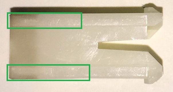
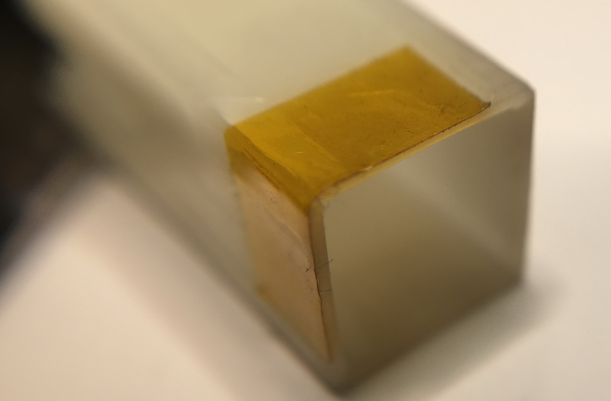
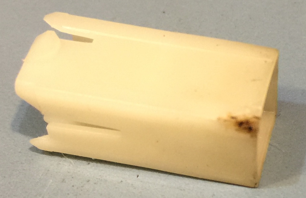
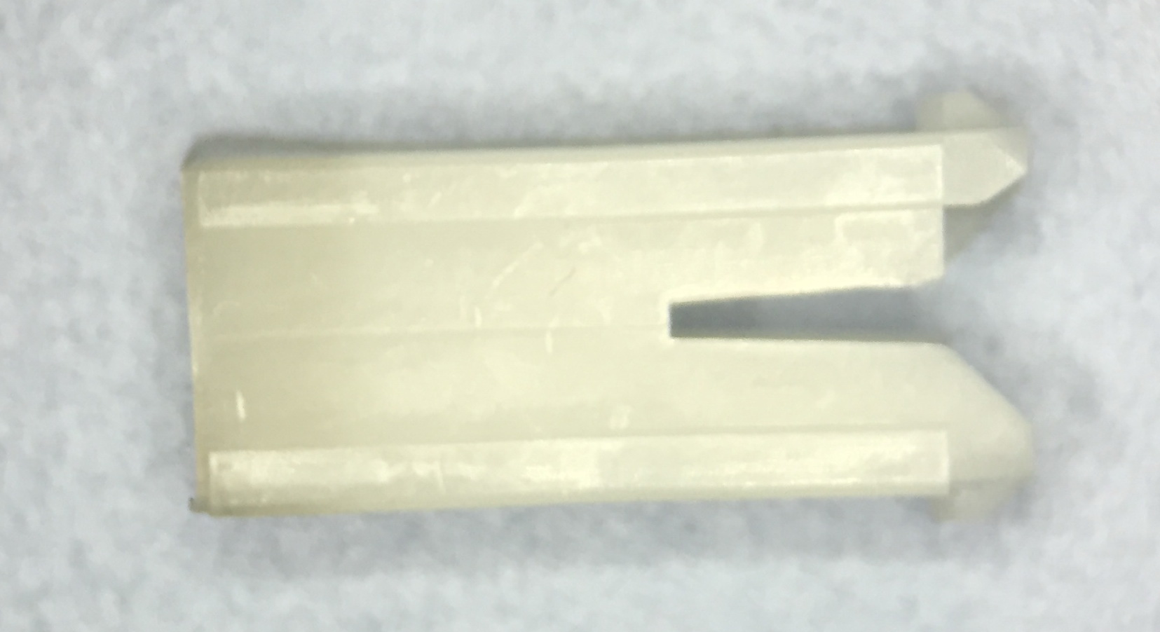
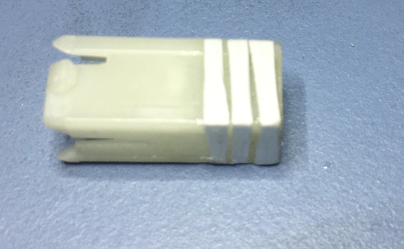
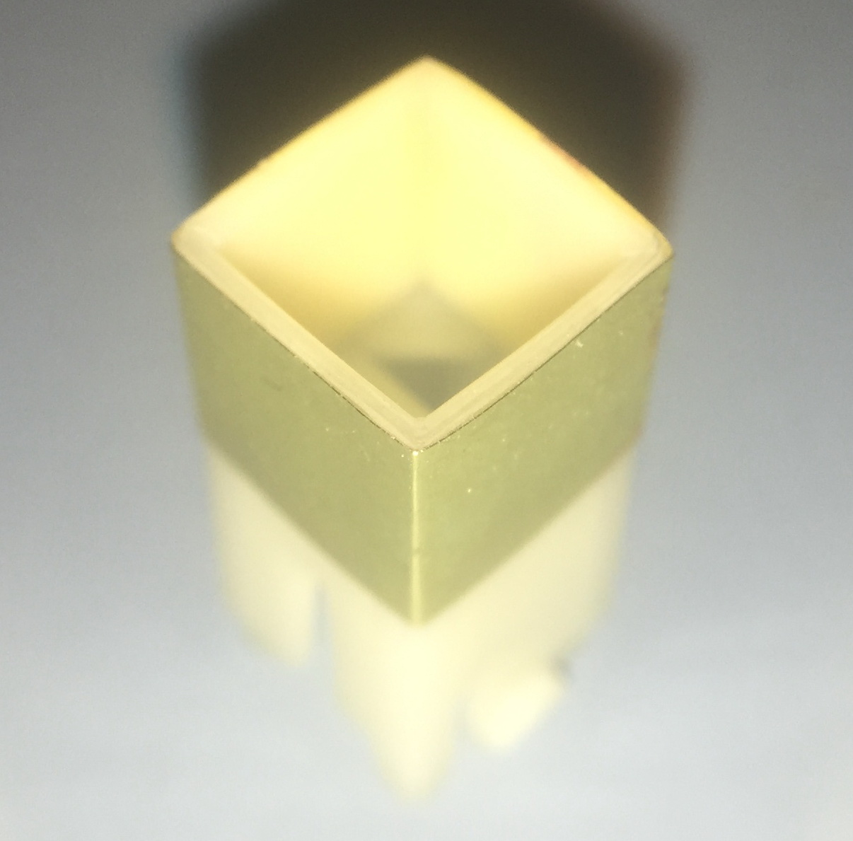
White plunger with the glide surface highlighted.
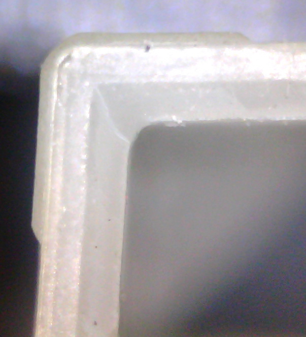
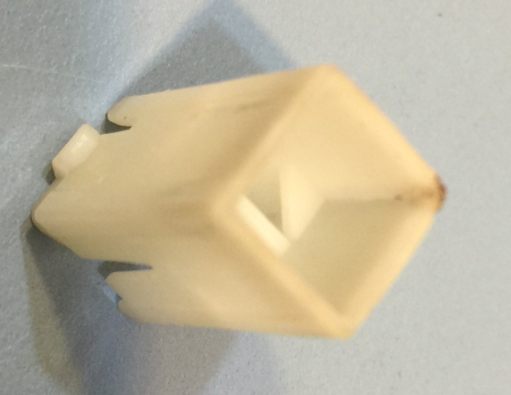
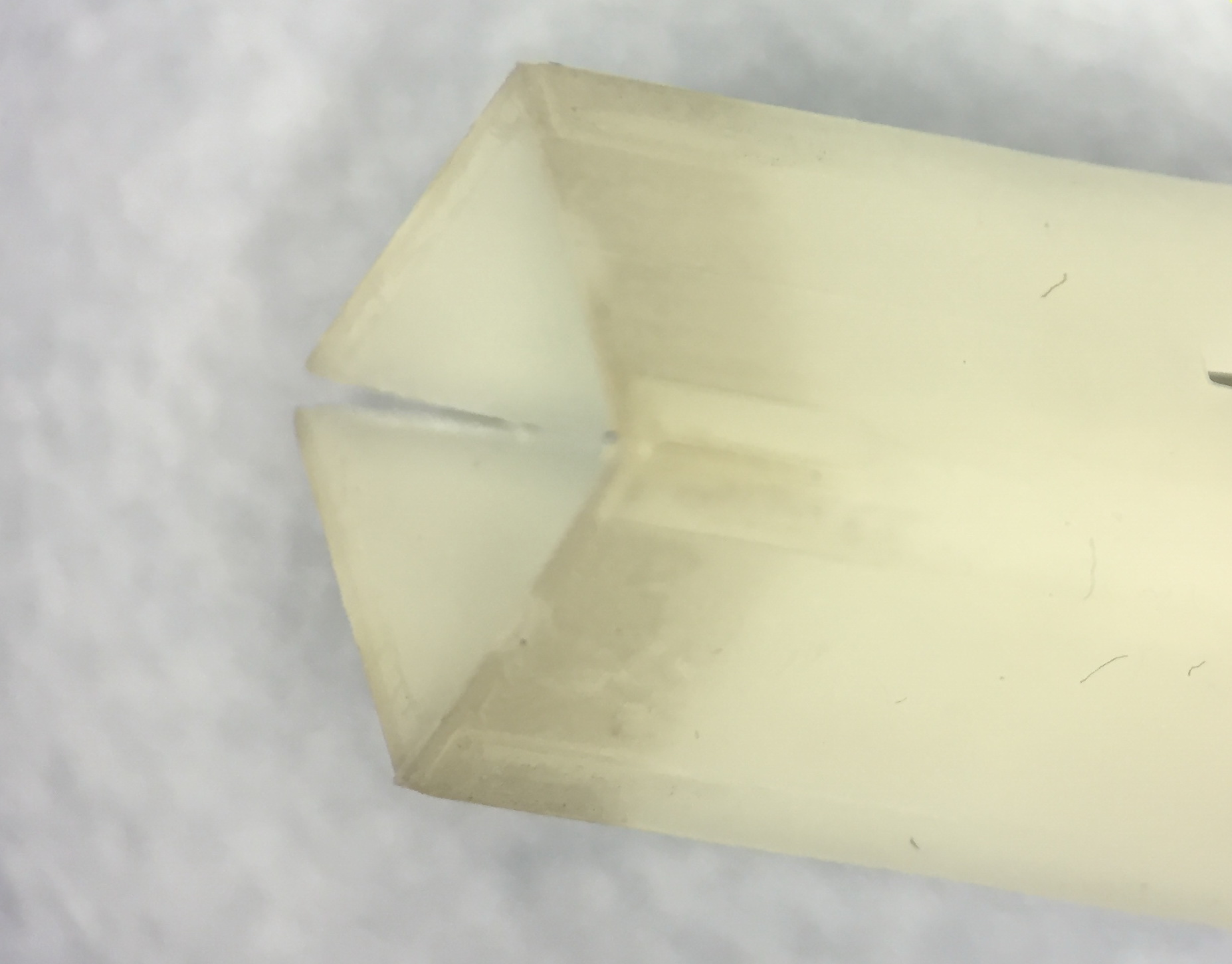
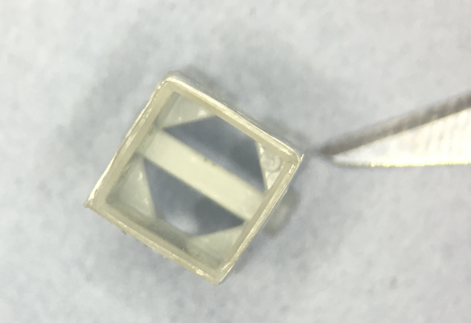
This is a zoom in on the end view of a corner of a plunger. The glide surfaces represent about 20% of the thickness of the plastic in the corners.
The glide surface is described in detail here, as it is the key to my repair strategy
The glide surface is about 0.004” (0.1 mm) thick, and 0.060” (1.5 mm) wide, and extend the length of the plunger. As the glide surface is on both sides of each corner, there are 8 of them. The glide surfaces can slide against the side of the well in the black plastic housing, but the total width of the plunger including the glide surfaces is less that the size of the well by about 0.008” (0.2 mm). There is no apparent wear on the glide surfaces. On each side of the plunger, the area between the glide surfaces is effectively recessed and never touches the wall of the well in the black plastic housing. The width of the plunger including the glide surfaces is 0.325” (8.25 mm). The width of the plungers from a recessed surface to the recessed surface on the opposite side is 0.317” (8.05 mm).
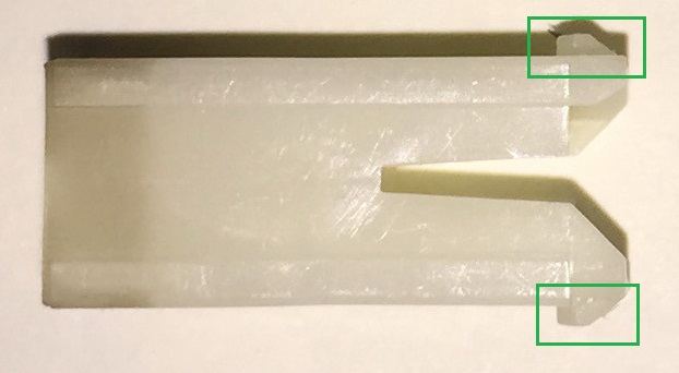
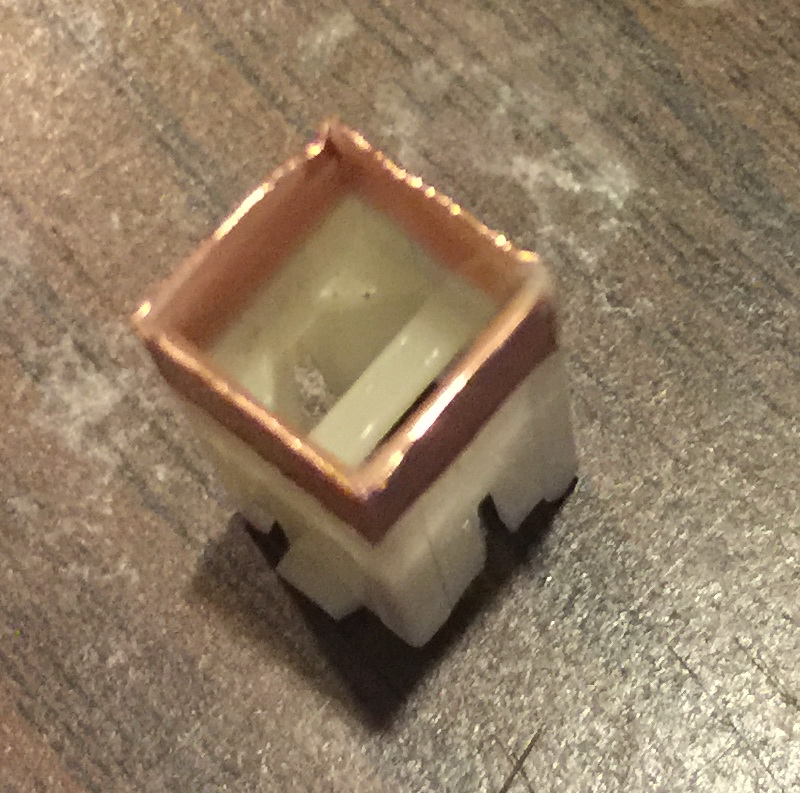
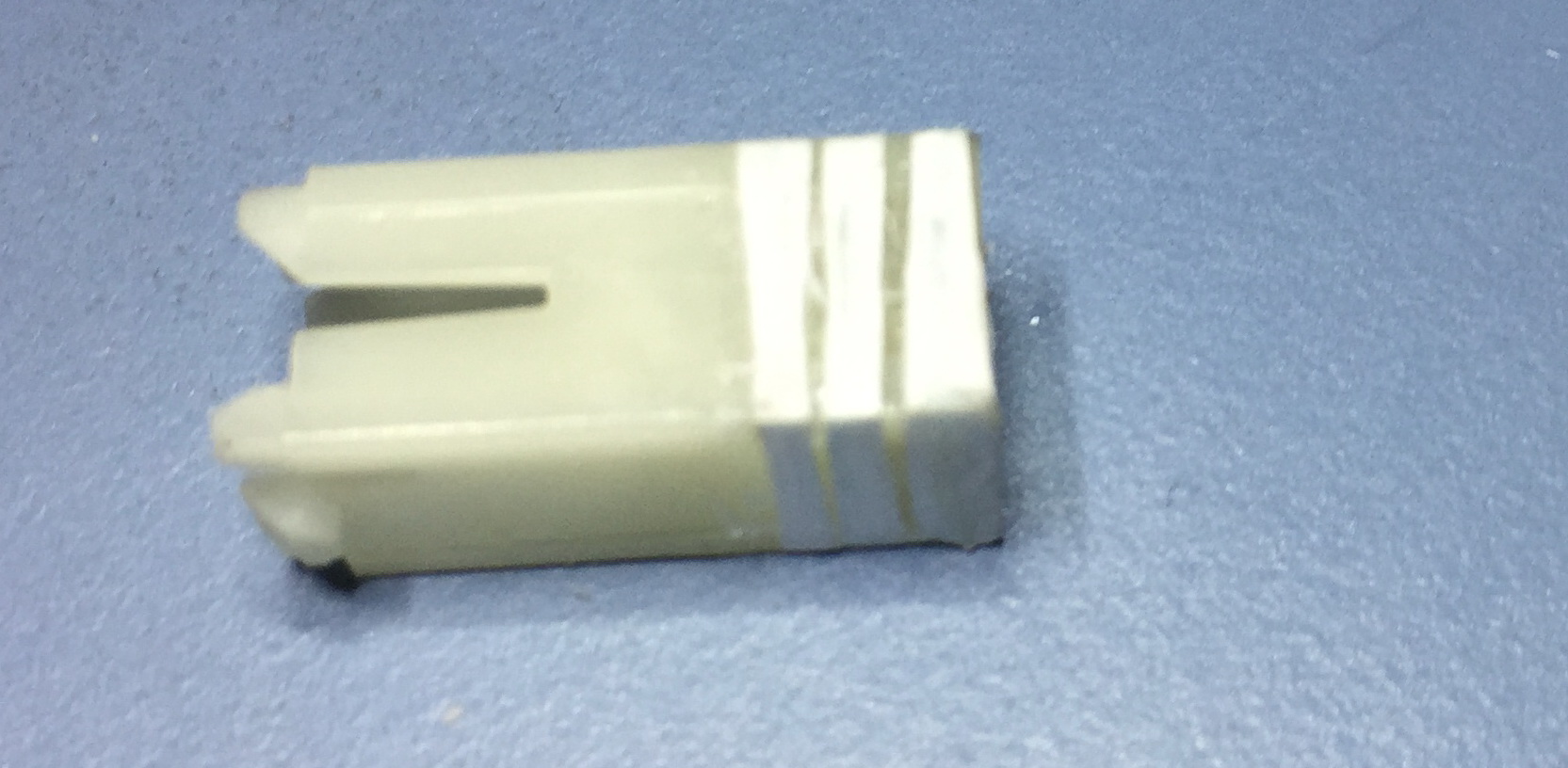
White plunger with retaining tabs highlighted. These retain tabs stop the plunger from coming out of the keyboard under normal circumstances.
Repairing the White Plungers with glue (Failure)
I tried multiple glues to try and repair the cracks in the plungers, including all five Epoxy adhesives and two Cyanoacrylate adhesives listed on this page Materials. All failed to provide structural improvement to the plungers and hold the cracks closed, once the key cap was inserted into the plunger.
HiTek Plungers repair Overview
The strategy for the the following White HiTek Plungers (as found in the HP-85 Keyboards) all use the same strategy:
Removing the glide surfaces on the damaged plungers. This provides some space for some type of supporting material to close the cracks in the plunger and inhibit any new cracks.
Apply some supporting material around the outside of the plunger. The supporting material, including adhesives has a maximum thickness of 0.004” (0.1 mm). This is the thickness of the removed glide surfaces.
The supporting material must not affect the sliding behavior of the plunger. It should have a height that exceeds the exposed part of the plunger, so that the bottom edge of the support material is always within the well of the black plastic housing. Otherwise it might catch the top lip of the well.
Machining the Plunger Corners (Failure)
My first attempt to remove the glide surfaces was to make a fixture to hold the damaged plungers in a milling machine, and then remove the glide surface by milling.
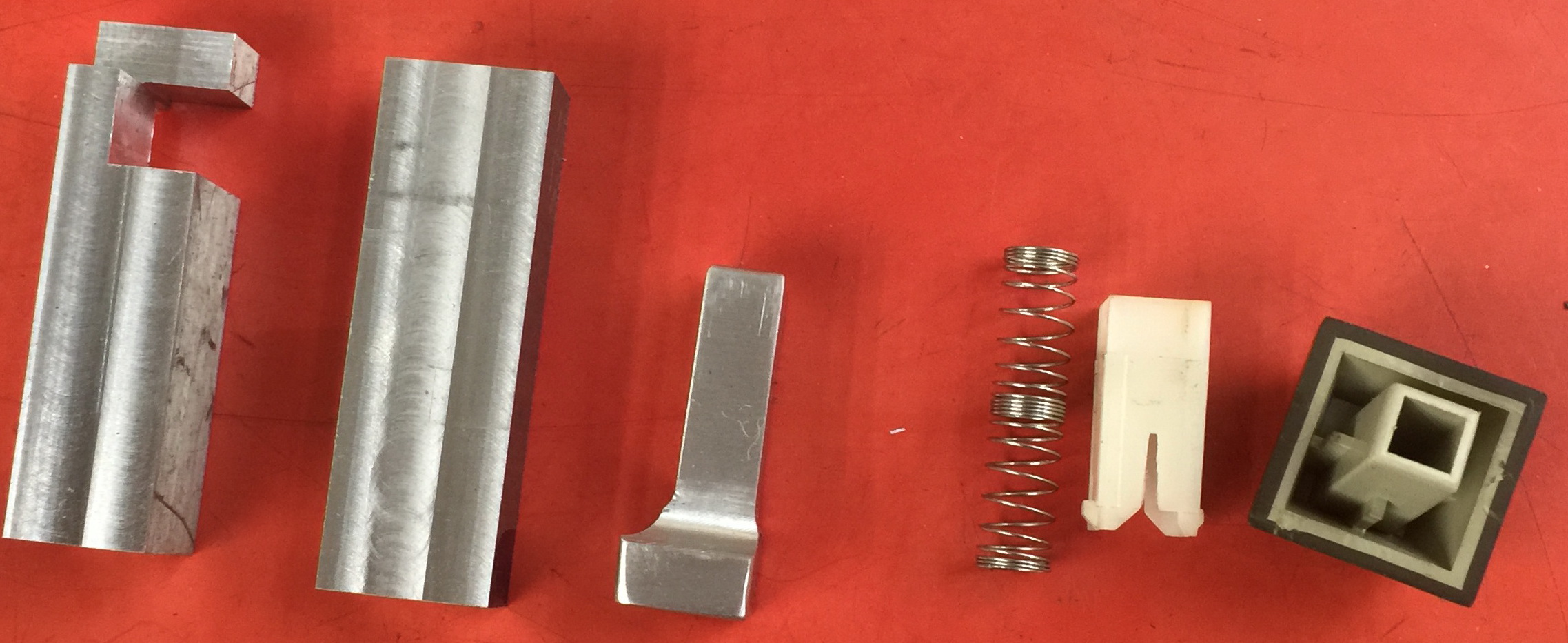
The fixture comprised a 3 sided support for the plunger, an insert that could be inserted at the top end of the plunger so that it would not collapse while being held in the fixture, and another flat piece of aluminum that supported the fourth side of the plunger.
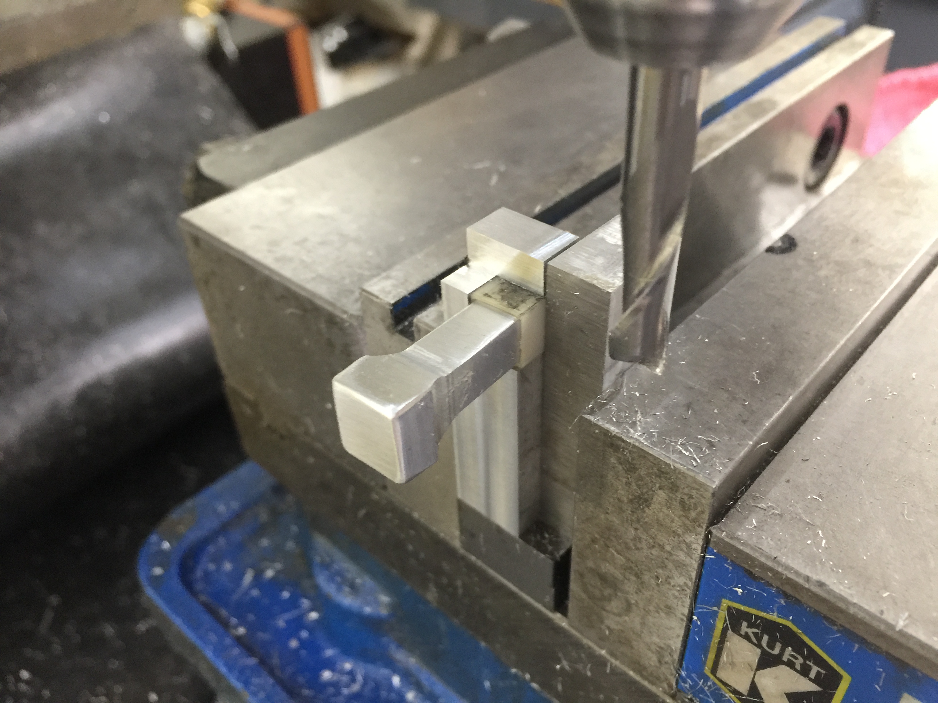
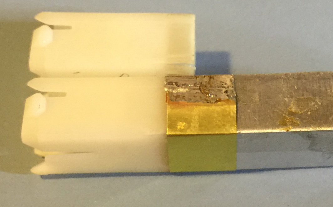
This shows the plunger and the fixture assembled in a vice, ready for the glide surfaces to be removed.
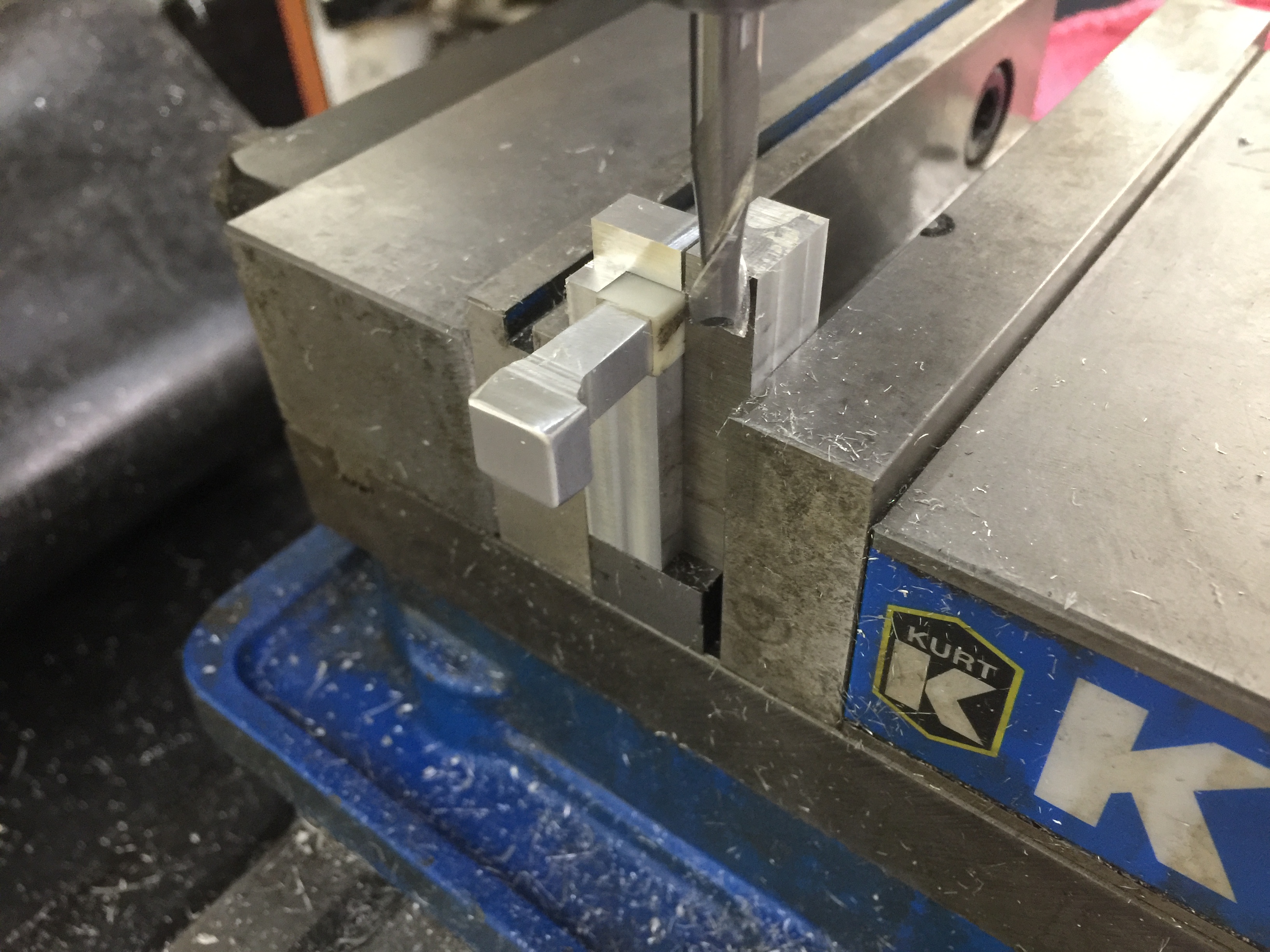
Unfortunately the plunger material is not very strong. Due to the crack in the plastic, the damaged area is bent outward, so when the milling cutter is used to remove the glide surface, the results are unpredictable, and often removed too much material. Also the material flexes during cutting and because the cutting tool (end mill) is designed to pull the cut material (chips) up, it tends to pull the plunger material up while cutting. This also means too much material is removed.
Trimming the Plunger Corners (Success)
The following process is very tedious, but gave good results, so this is what I did for all of the white plungers I repaired.
As described above, the aim is to remove the glide surfaces (8 of them per white plunger) to make room for supporting material. While more material can be removed (in the axial direction, not the depth direction), I chose to remove about 0.300” to 0.330” of the glide surface on all 4 sides of the plunger (8 glide surfaces). So what needs to be removed is 8 times 0.300” by 0.060” of plastic. The result is that for 0.300 of the plunger at key cap end the glide surface areas have been cut down to be flush with was the recessed area. I used a Swann Morton Scalpel Handle number 3 with Swann Morton Number 11 Scalpel Blades. I probably replaced the blade every 5 to 10 plungers.
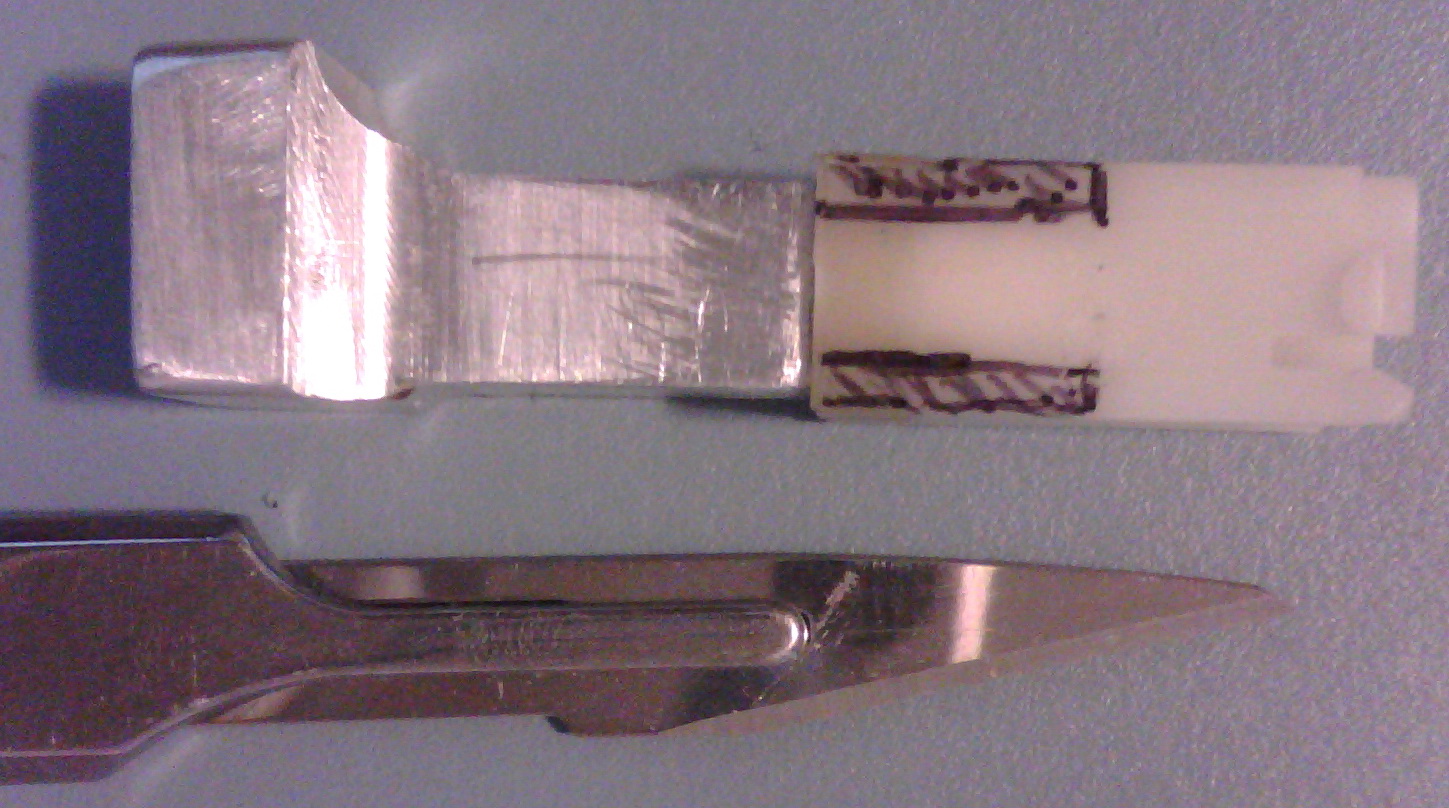
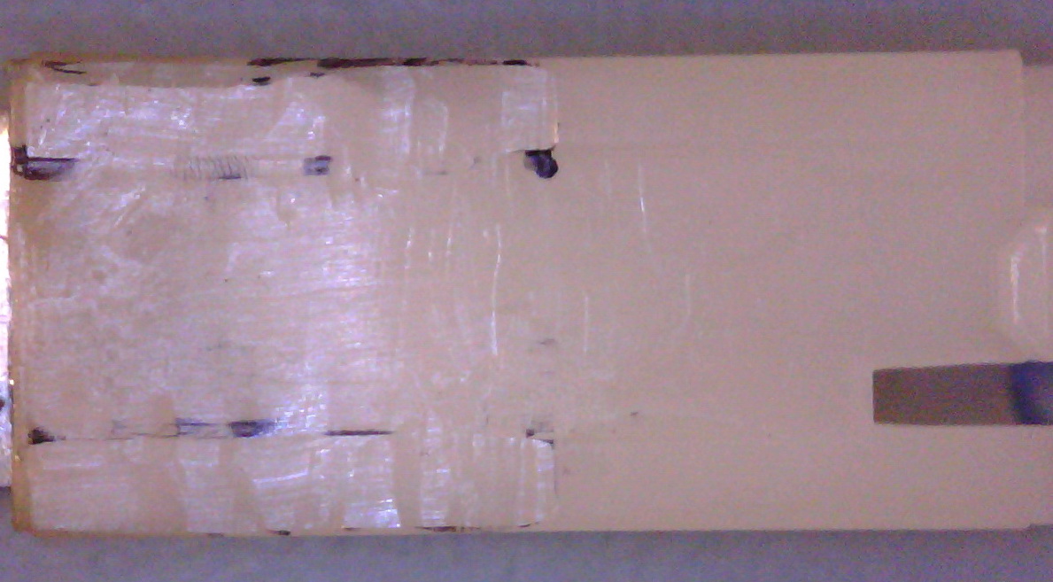
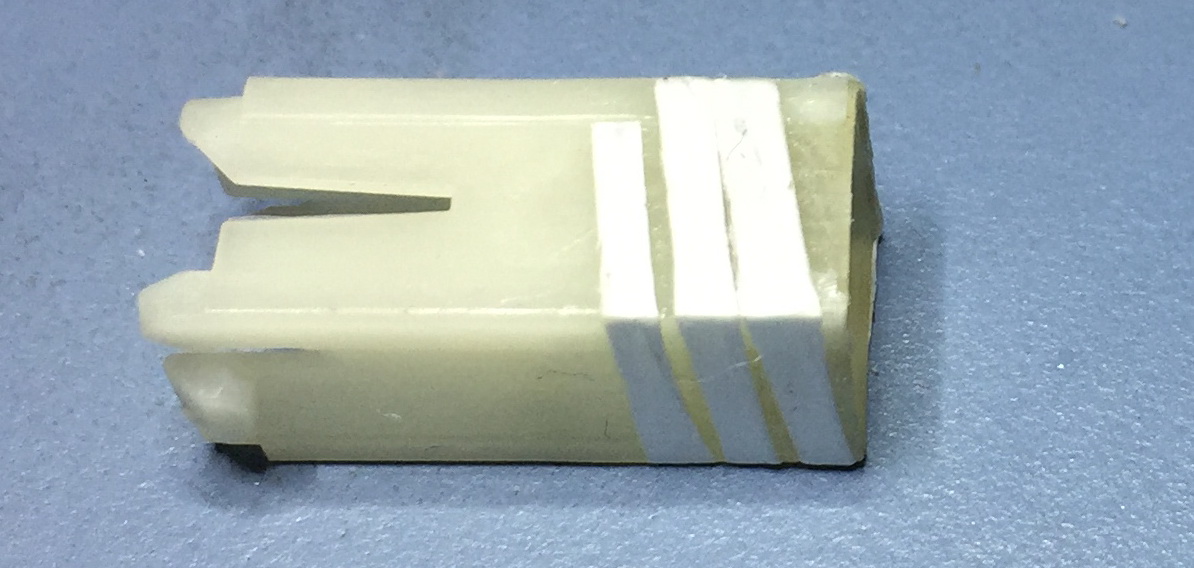
To support the walls of the plunger and to be able to hold it better, I used the Aluminum insert from the failed machining attempt described above. The insert has a square cross section measuring 0.268” from side to side. You will note that it is much wider at the end, and this proved to be a good safety stop when the scalpel slipped during the trimming operation, protecting my finger that was pressing on the end. I have highlighted the areas to be trimmed in black.
After trimming, the top 0.300” of the plunger is the all at the same level of the recessed area.
These are the shavings cut with the scalpel. It took about 2 minutes to trim these two glide surfaces. (after lots of practice)
Material #1: Copper foil (Failure)
Thin Copper foil with adhesive backing is readily available in various widths and is used for electrical shielding and also in making artistic stained glass panels. With adhesive it is about 0.003” thick.
I wrapped a single layer of foil around the plunger in the prepared area, starting at the corner that is opposite the corner with the crack. This means the middle of the tape is across the crack and the maximum length of adhesive tape is to either side. This is not possible with plungers with 2 adjacent cracks or 2 opposite cracks.
This plunger has 2 cracks and if you look carefully, there is only 1 side worth of tape from a crack to the end of the tape.
I tried several times to make this work. They all failed with the tape splitting as soon as the key cap was inserted into the top of the plunger.
Material #2: Kapton tape (Failure)
Kapton tape with adhesive backing is another common electrical assembly material known for tolerating high temperatures and being unaffected by almost all chemicals. While it was much stronger than the previous experiment with copper foil, it still failed. In this case the failure is that after installing back into the black plastic body of the keyboard, over time the adhesive slowly sheared allowing the crack to re-open.
Material #3: Melted Nylon (Failure)
This attempt does not require the removal of the glide surfaces. The idea for this repair was to melt some additional Nylon into the area of the crack and hold the sides of the plunger appropriately as the melted material solidifies. Unfortunately, I was doing the heating with a fine tip soldering iron and even the lowest temperature setting was burning the Nylon. Maybe with a lower temp tool, this technique might have worked, but I didn’t have such a tool, and I moved on to my next experiment.

Material #4: Glide Dental Floss (success)
This process appears to be successful, but I don’t have any long term data to support this hope. After the previous failures with Copper Foil and Kapton, I searched for a strong thin material that I could use to strengthen the plunger and close the crack(s).
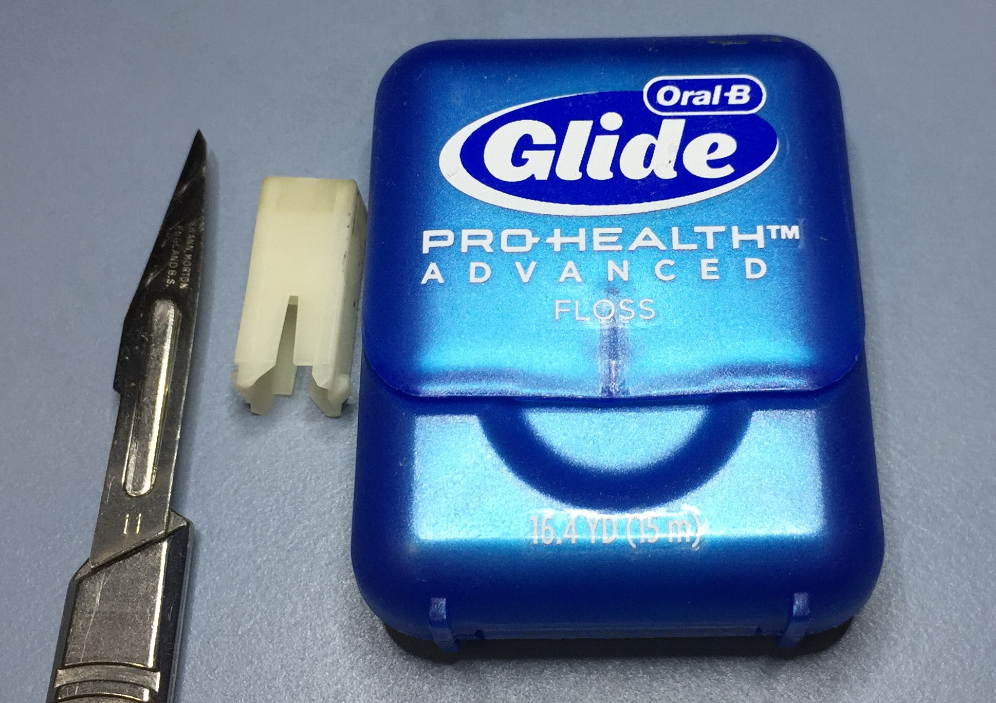
Glide Dental Floss is very thin, and
strong. It is made of a folded over tape of
polytetrafluoroethylene
(Teflon)(PTFE).
You can read much more about PTFE here
Comprehensive Guide on Polytetrafluoroethylene
Also shown is the Scalpel and a plunger.
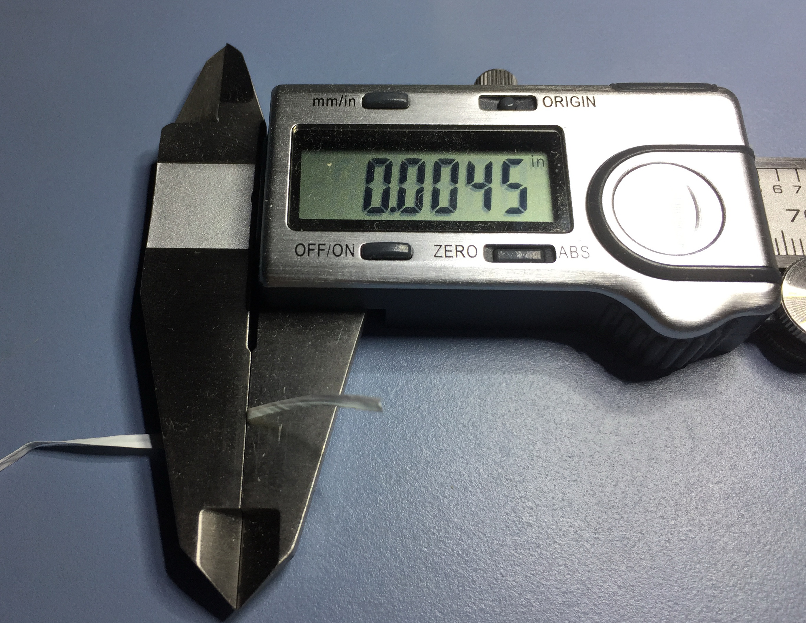
Even folded over, it meets my requirement of being about 0.004” thick (0.1 mm).
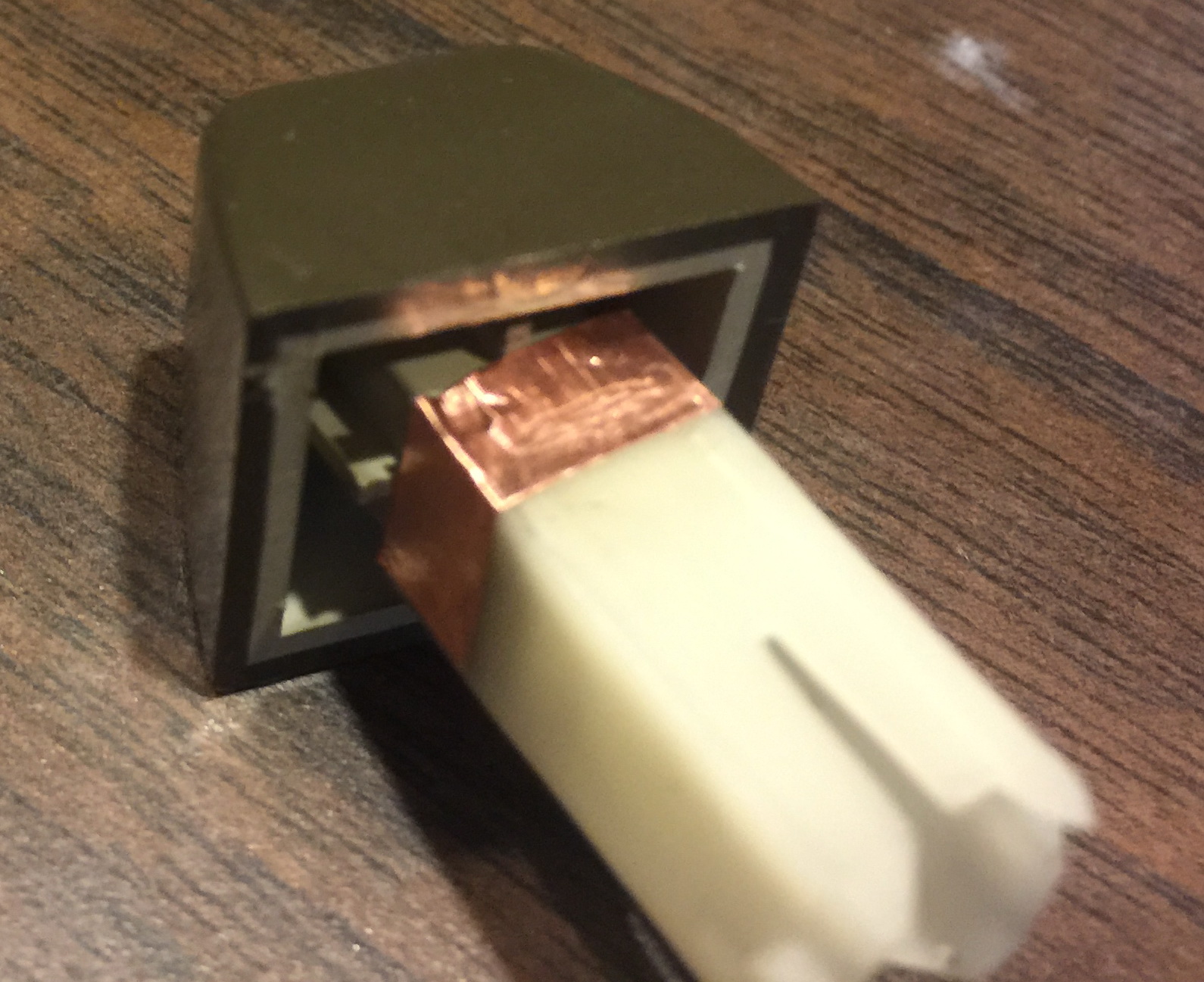
The plunger prior to trimming the glide surfaces and then applying the Glide Floss. (sorry for the two unrelated uses of the word glide)
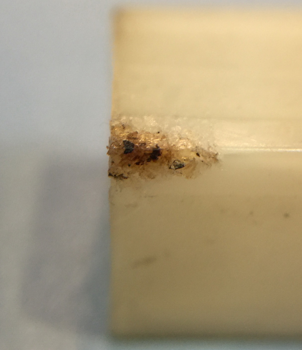
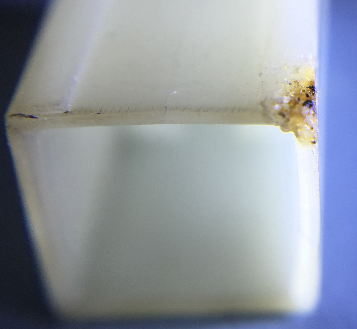
Close up view of the crack in the plunger that causes it to stick in the black plastic housing
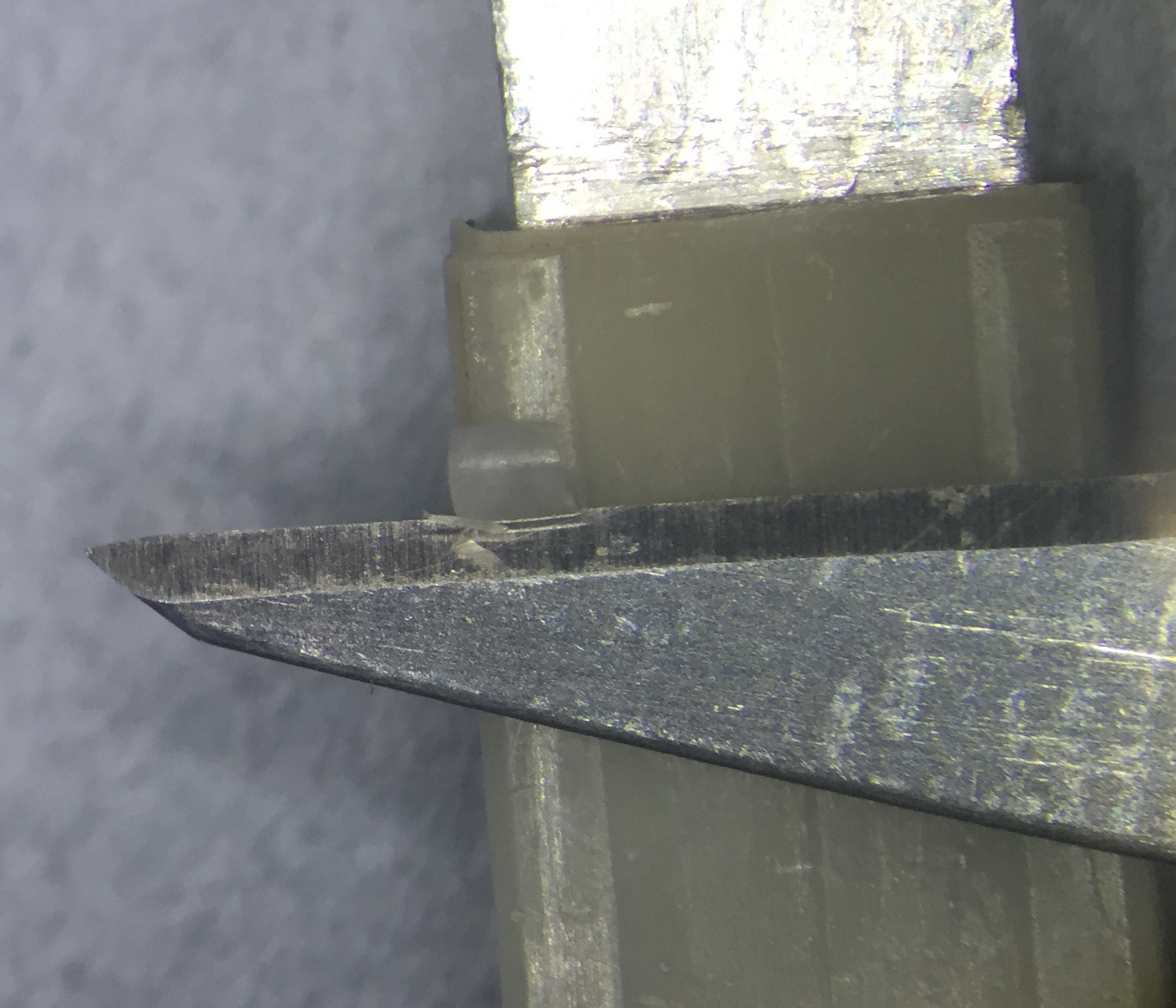
Start of trimming the 8 glide surfaces (2 per side). About 0.300” of the surfaces need to be trimmed off. This takes time to do, and needs to be done carefully, so as to not take off too much material. The metal insert that I push into the end of the plunger, give it extra support while I am doing the trimming, and the flaired end protects my fingers if I slip with the scalpel. While trimming, I hold the plunger and insert with thumb and first finger of one hand, and the scalpel in the other hand.
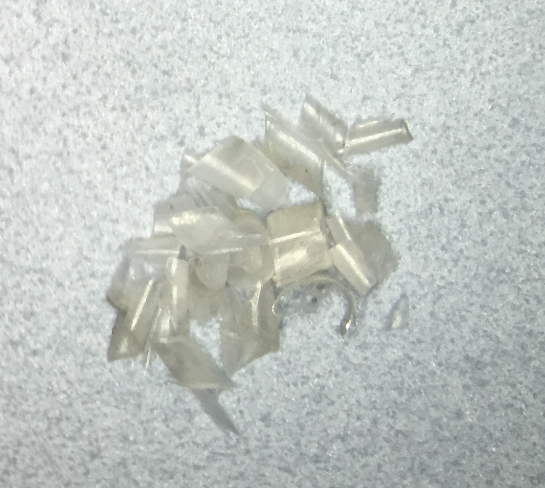
The plastic removed from the 8 glide surfaces.
For the first step of working with the Glide Floss, some extra preparation is needed. The glue that I have used is Loctite 4014. As note in the 4014 section, I don’t dispense this glue from the normal dispensing tip. Instead, I dip a very fine probe into the bottle just deep enough to get a small drop on the tip/side of the probe. I then have a few seconds to place it on one of the two surfaces (the plunger) that I am joining and then bring the second surface down onto the top of the placed drop (in this case, it is the Glide Floss). This means I need to prepare carefully so that the Cyanoacrylate adhesive does not sets (actually polymerizes) before I have time to place the Glide Floss. This means cleaning any debris leftover from the trimming task just completed, and stretching out the Glide Floss and making sure there are no twists in it. I have also found it handy to have a small pile of strips of Laser Printer paper that are 1/8” x 2” (2mm x 50 mm). These can be dipped into excess 4014, and will wick it up. Also, since the 4014 bottle will be open without its dispensing nozzle, take whatever precautions you feel are appropriate to avoid knocking it over while working on the plunger. When you are done, remember to screw the cap back on tightly and return it to the fridge.
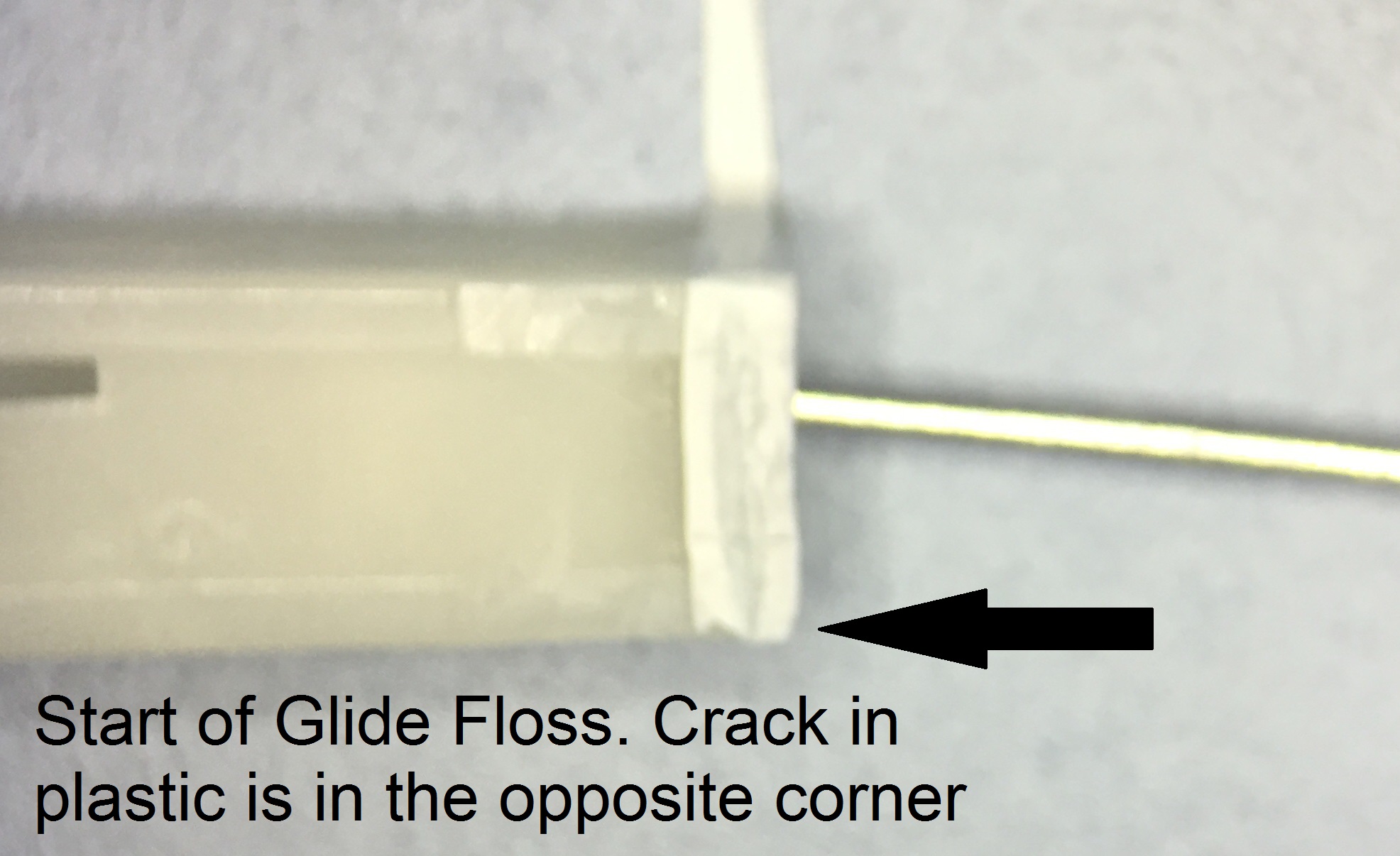
The start of the Glide Floss is glued to the corner that is furthest away from the crack. This maximizes the amount of floss that will be glued prior to getting to the crack and after it. I don’t know if this is critical, but it worked for me. So with everything ready, place a small drop of 4014 on the plunger and then place the beginning of the floss on top of the drop. Then press down with the probe or some other tool so that the glue layer is as thin as possible.
After the the initial drop of 4014 has set, pull the floss taught around the first 2 surfaces and then add a small drop of 4014 to the side of the floss on these sides of the plunger. It should wick into the tiny gap between the floss and the plunger. Wick up any excess 4014 with the paper strips. Wait for the 4014 to set. The floss should now be well attached to 2 sides of the plunger. These are sides 1 and 2.
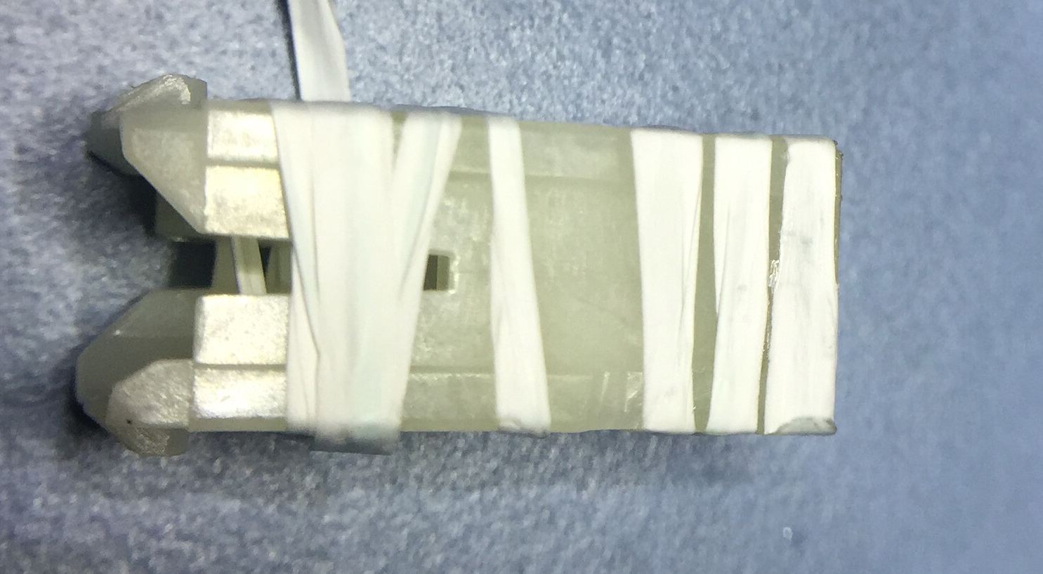
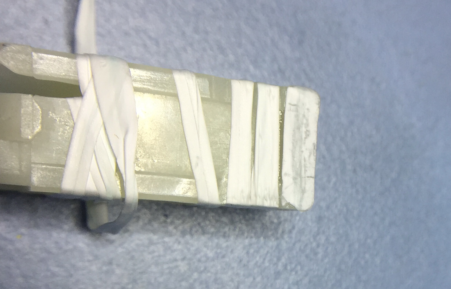
Now wrap the floss around the plunger for 3 complete turns, leaving a small gap between the floss so that we can apply more 4014 in a following step.
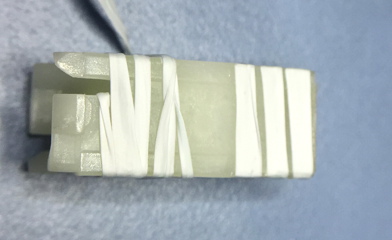
This is side 3
When wrapping the floss on side 4, it must be done at an angle so that on the following side 1, it does not overlap the floss that is already there. Keeping the floss taught, wrap it around the end of the plunger so that it does not unwind.
Check the following:
The floss is tight
There is a gap between the turns of the floss on all 4 sides of the plunger
The crack(s) has been closed up
Make adjustments as necessary, using a pointy probe. Now place a small drop of 4014 into each of the gaps between each floss turn on all 4 sides. You should see the liquid wick into the very small gaps under the floss. If you accidentally add too much 4014, wick it up with the thin strips of paper.
Allow a few minutes for all of the 4014 to set. Unwind the excess floss at the bottom of the plunger and neatly cut the floss at the end of the 3 glued turns. You may need to add a small amount of 4041 to the end to make sure it is attached.
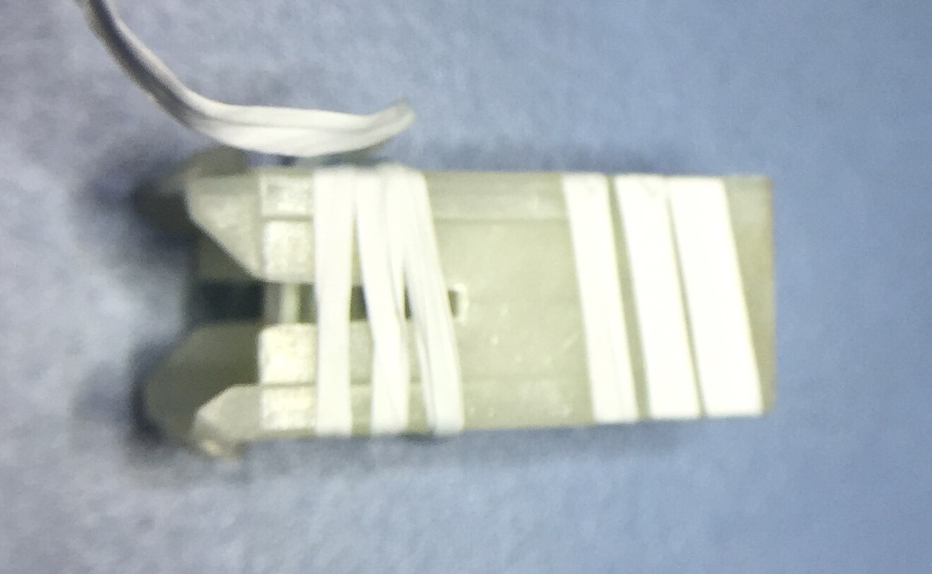
Side 1 finished
Side 2 finished
Side 3 finished
Side 4 finished
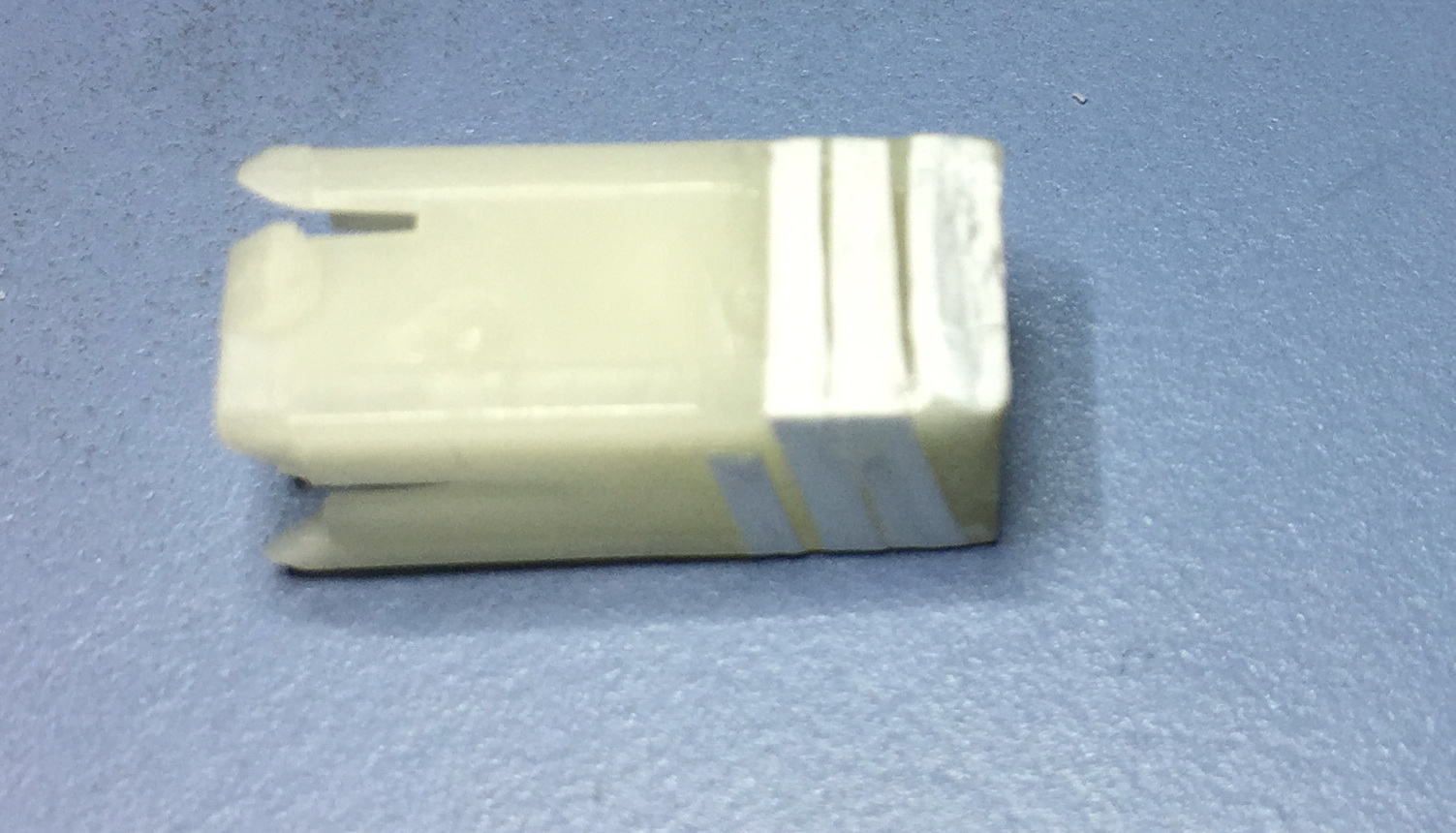
End view of the repaired plunger. The scalpel blade is pointing at the corner with the crack.
Test fit the plunger by checking it slides easily in the black housing. You can do this by sliding it in upside down. If it doesn’t slide, figure out what the problem is and adjust as necessary. If the issue is that the glide surfaces weren’t trimmed enough, you can unwind the floss and peel off the 4014, which is quite brittle when set.
Repairing with Plumbers Tape (unknown)
The common white plumber’s tape that is wrapped around threaded pipes prior to joining to matching fittings is made of the same material as Glide Floss. As it is typically 0.5” (12.7 mm) wide, maybe a single wrap of it, in combination with Loctite 4014 might be a solution. This would still require the trimming of the glide surfaces. It would require a different strategy for the applying the tape and the 4014. Maybe place a drop of 4014 on one of the sides of the plunger, apply the tape and press it down to squeeze out as much glue as possible due to the clearance requirements. Once it has set (maybe wait a minute), pull the tape taught around the second surface and apply a second drop of glue that should wick into the tiny gap between the tape an the second surface. The tape would need to kept taught till the glue had set on the second surface. This sounds like you will be needing 3 hands:
One to hold the plunger
One to pull on the tape
One to apply the glue.
I don’t have a good solution for this. The corner between surface 2 and 3 is the one with the crack (assuming you started in the right place). This time, the pulling the tape taught for gluing to the third surface is also closing up the crack, so this is probably the most critical step. Finally the fourth surface can be taped and glued. As this tape is thinner than Glide Floss, it may be possible to do a second layer.
If anyone tries this procedure and it turns out to be successful, please take photos of how you did it (fourth hand?) and send it to me so I can update this page.
Repairing with Brass Shim Girdle (success)
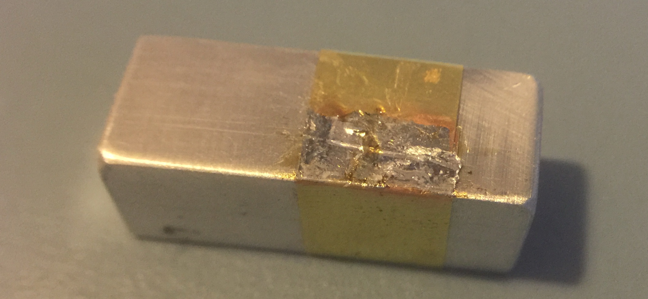
This repair process is similar to the Copper Foil except it works, it seems very reliable, and does not depend on adhesives (except solder). A thin brass girdle that is slipped over the damaged white plunger that has had the glide surfaces removed.
The girdles are made from strips of brass shim that is 0.0015” (0.038 mm) cut into strips 1.36” (34.5 mm) long by 0.220” ~ 0.250” (5.6 ~ 6.4 mm) wide. The ends of the strip of brass shim are joined with a lap joint using solder. You will also need a square cross section bar (or former) to get the correct shape. It should have a cross-section of 0.320” x 0.320” (8.1 mm). I made mine out of aluminum (aluminium), but it could be any material that is solid, can tolerate soldering temperatures for a short time, and can’t be soldered to. Copper, brass, bronze, plastic, and glass are bad choices. Aluminum, titanium, stainless steel, hardwood (maybe) are good choices. The cross-section dimensions are critical, so target +/- 0.001”.
When trimming the glide surface on the plunger, you must remove at least as much as the width of your brass strips. To get the best lap joint I found that using very thin solder helped. In my case I started with solder that is 0.010” (0.25 mm) diameter, and using a roller and a hard surface, I created solder tape that is about 0.020” (0.5 mm) wide and only 0.004” (0.1 mm) thick. See the second picture below.
The black clamp you can see in several pictures is called a Tool Maker’s clamp, they are inexpensive and are available from many sources. Google is your friend.
All the images on this page are thumbnails. Click to get higher resolution images.
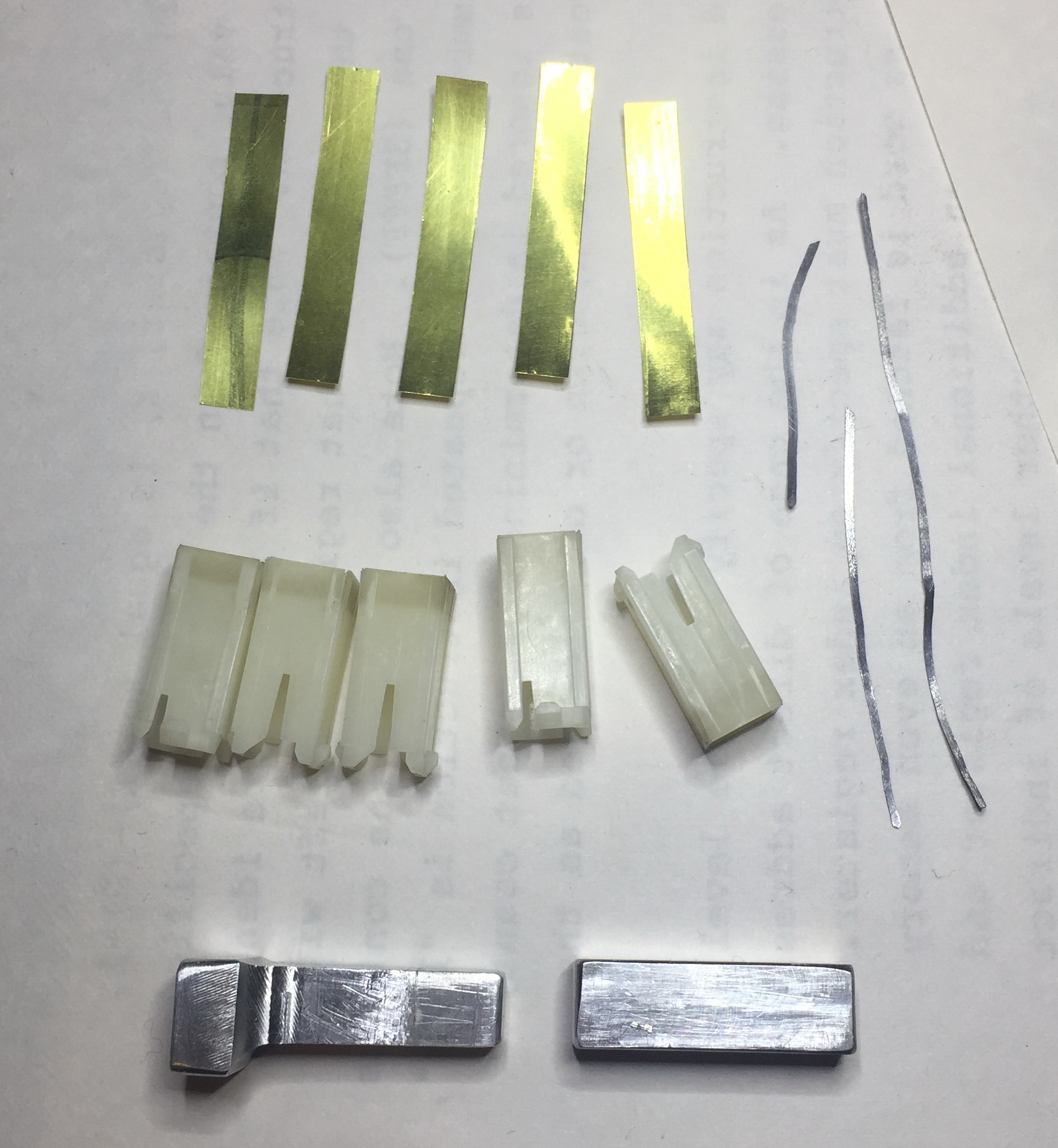
Getting ready to make some brass girdles. Brass shim stock, 0.0015” thick cut to strips 0.22” wide by 1.36” long. Although this is metal, it is thin enough to be cut with good quality scissors. The aluminum bar in the bottom right of the picture is about 1” long and 0.320” x 0.320” cross section. The aluminum in the bottom left of the picture is used in the glide surface trimming operation. You will also need some white plungers with a crack in one or more corners. Many HP-85 owners have a good supply of these.
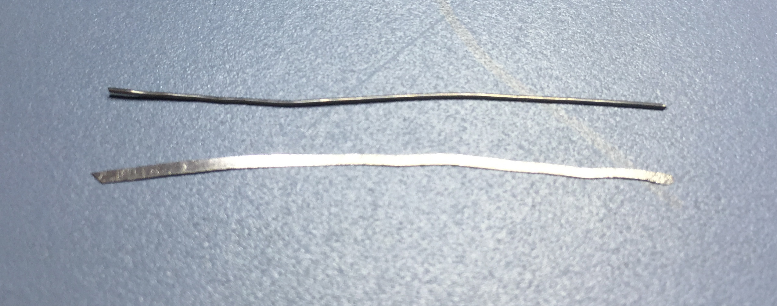
Normal rosin core solder 0.010” diameter. Before and after rolling it flat.
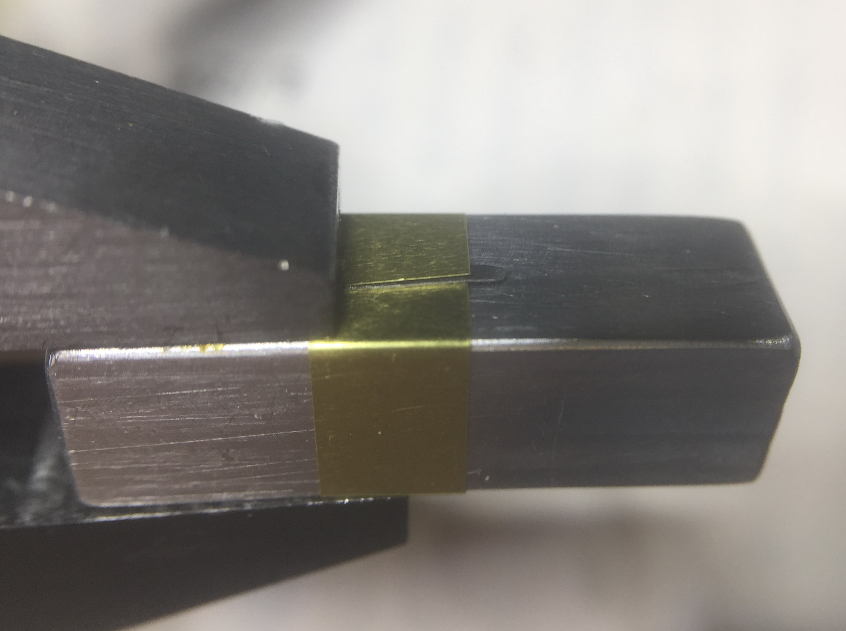
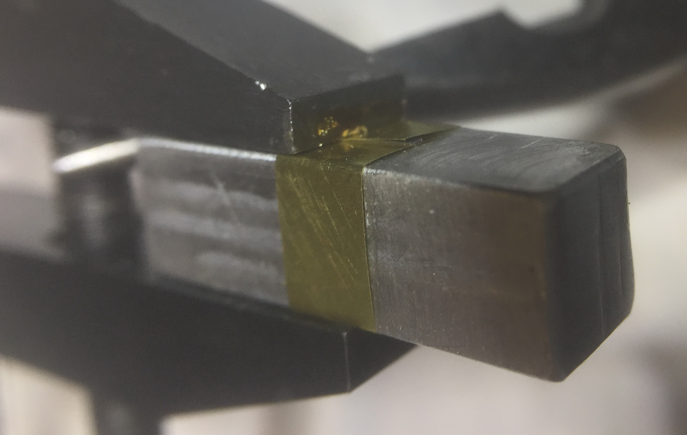
Take the brass shim strip and wrap it around the former very tightly, with the overlap in the middle of one off the sides, not at an edge of the former. Hold it in place using the machinist’s clamp, exposing a bit more than half of the width of the shim strip.
If you have never used a machinist’s clamp, there are several ways to use it, but the technique that is best for this application is using only edge pressure at the tip. First adjust the rear spindle so that does not engage the far jaw. Then adjust the Other spindle (nearer to the tip) so that the if the jaws were parallel they would be slightly wider apart than the objects being clamped. If the rear spindle is now adjusted to create the clamping action, only the tip of the jaws will be pressing down on the brass shim. This minimizes the heat sinking effect of the clamp, which makes soldering easier.
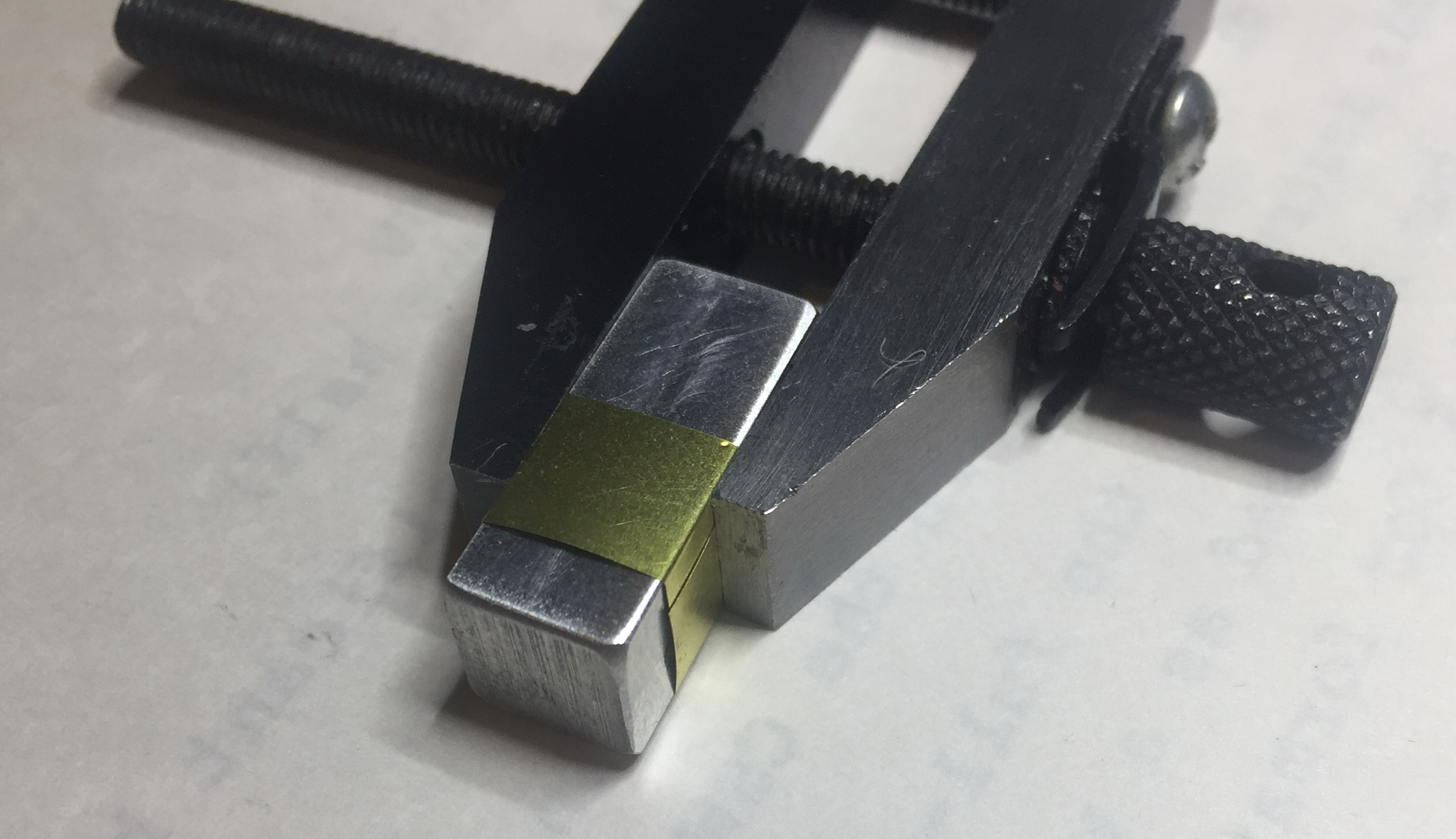
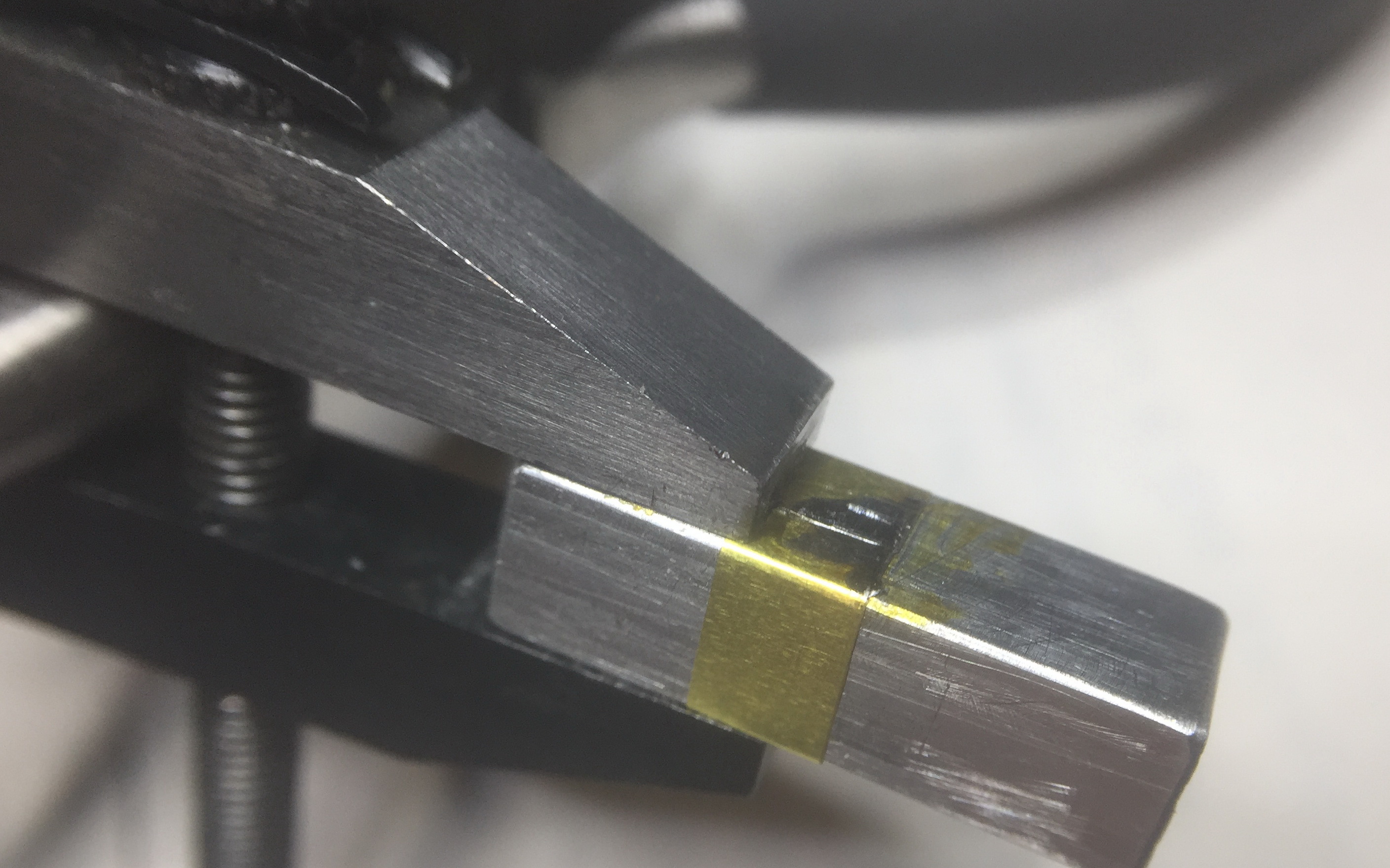
Another view of the clamped assembly prior to soldering.

Place a piece of the solder tape into the lap joint then add some liquid rosin flux (never acid flux). Adjust the position of the solder then trim off any that is not within the joint, as we don’t want too much solder.
Trimmed solder, ready to be soldered.
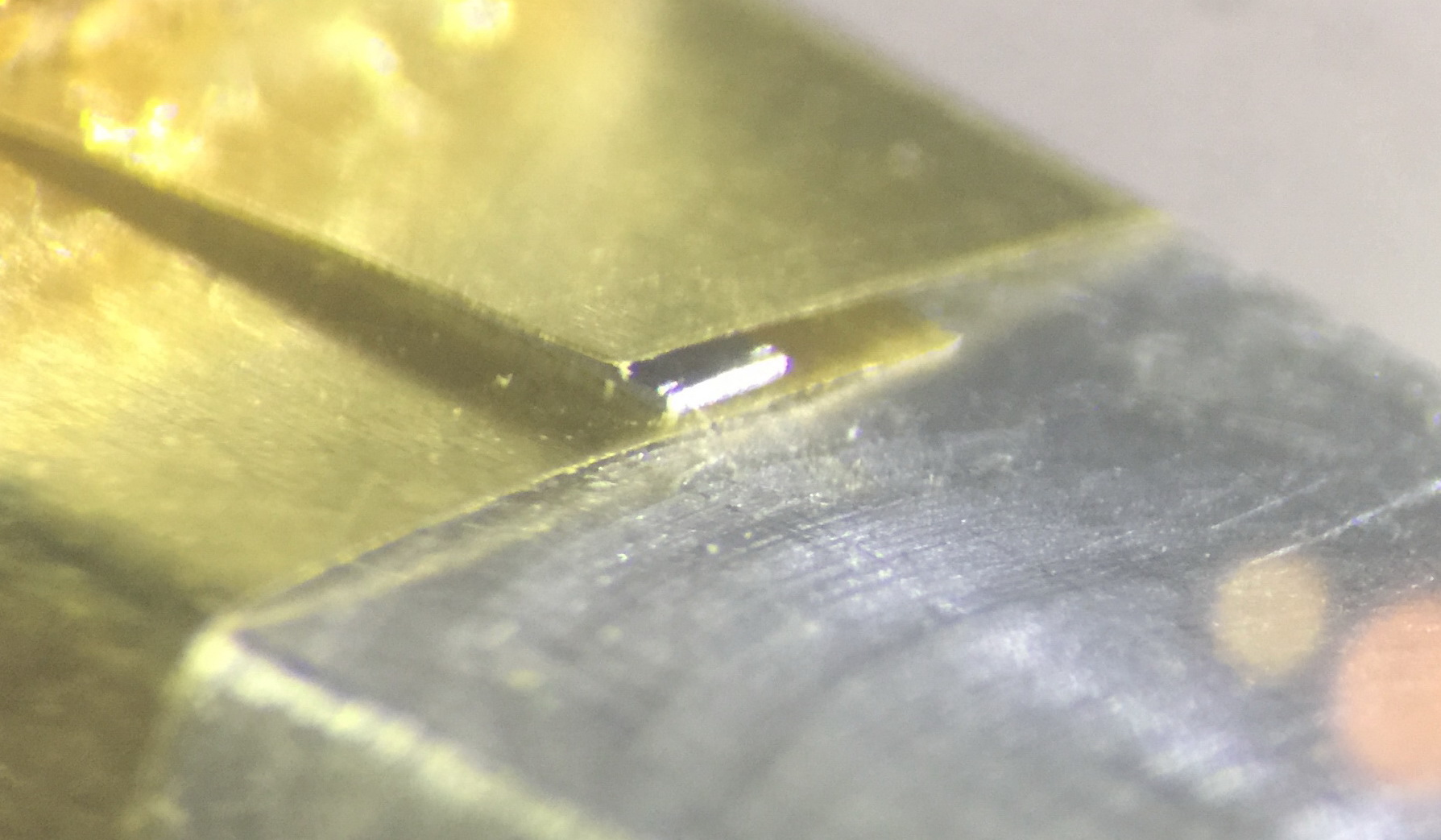
Close up view of the trimmed solder, ready to be soldered.
Solder the lap joint. Since the aluminum former is a good heat sink, a fairly high wattage soldering iron may be needed, or one with very good temperature control. If you are using a Metcal, a STTC-117 tip works great. The goal is a very flat joint. You may need to press down on the joint with a stainless steel probe while the solder is melted, and keep pressing until the lap joint has cooled down.
Now that half of the lap joint is complete, rotate the assembly in the clamp to expose the unsoldered half, and repeat the process.
If you are unfamiliar with machinist’s clamps, the right way to loosen and re-tighten the clamp is to do it by only adjusting the rear spindle, keeping the jaw spacing set by the other spindle unchanged.
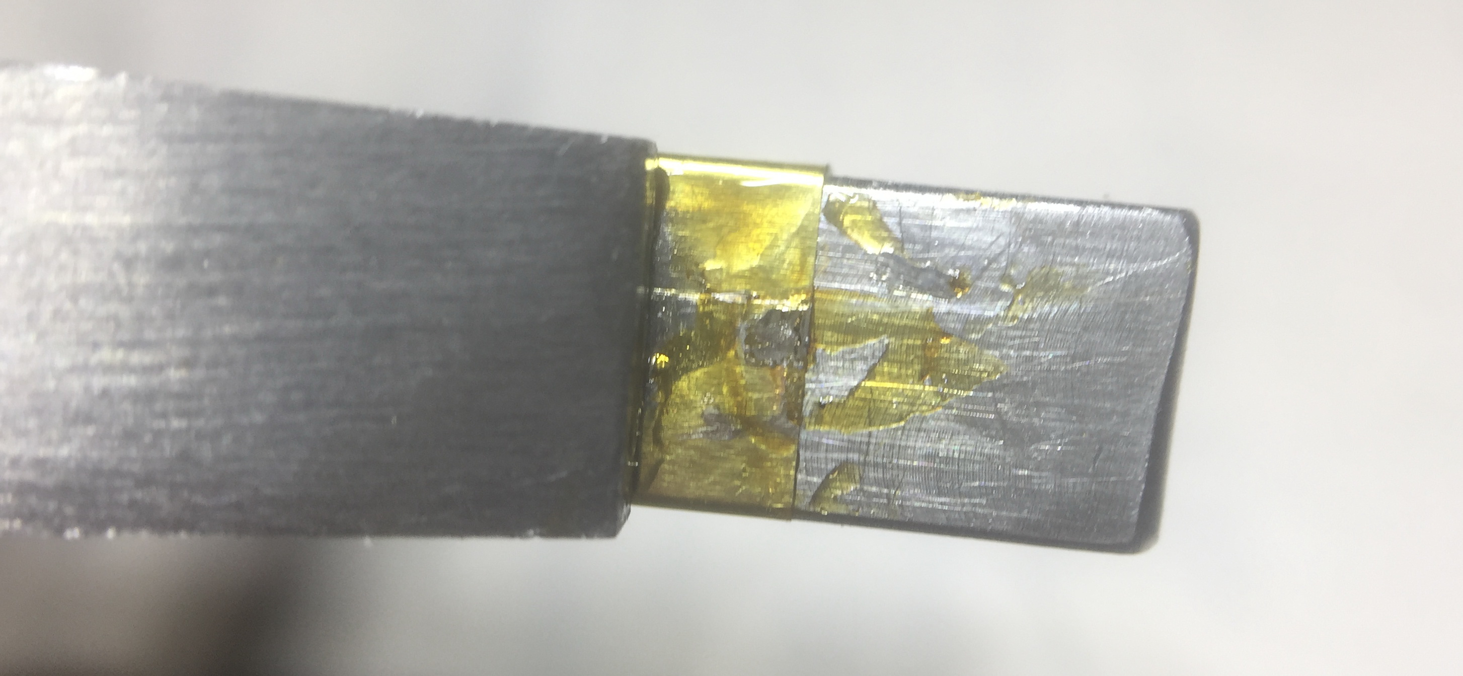
The finished lap joint. Time to clean off the excess flux and remove it from the former.
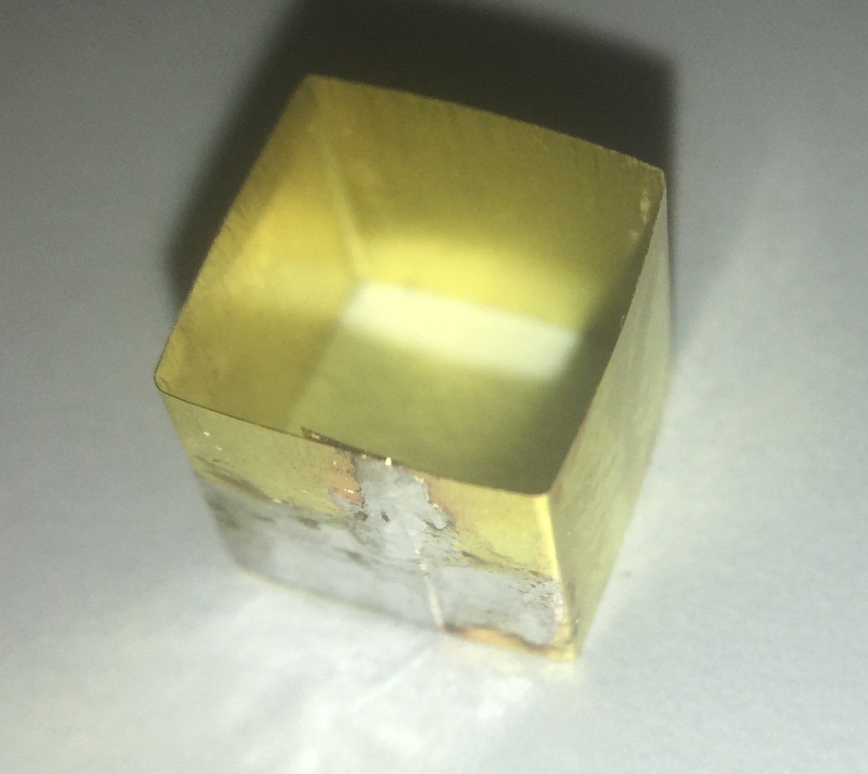
The finished brass shim girdle.
Now slide the girdle over the damaged plunger. I found it helpful to first slide the girdle back onto the former (after all the flux has been removed). This protects it from being crushed or deformed as you get things lined up for moving it onto the plunger. I also found that sometimes it helped to file a very small bevel on the plunger to help getting started with sliding the girdle on. Once it has been slid onto the plunger, you may optionally add a drop of 4014 glue.
The final result, looking at the nice sides without solder.