Keyboard Plungers
All the images on this page are thumbnails. Click to get higher resolution images.
Background
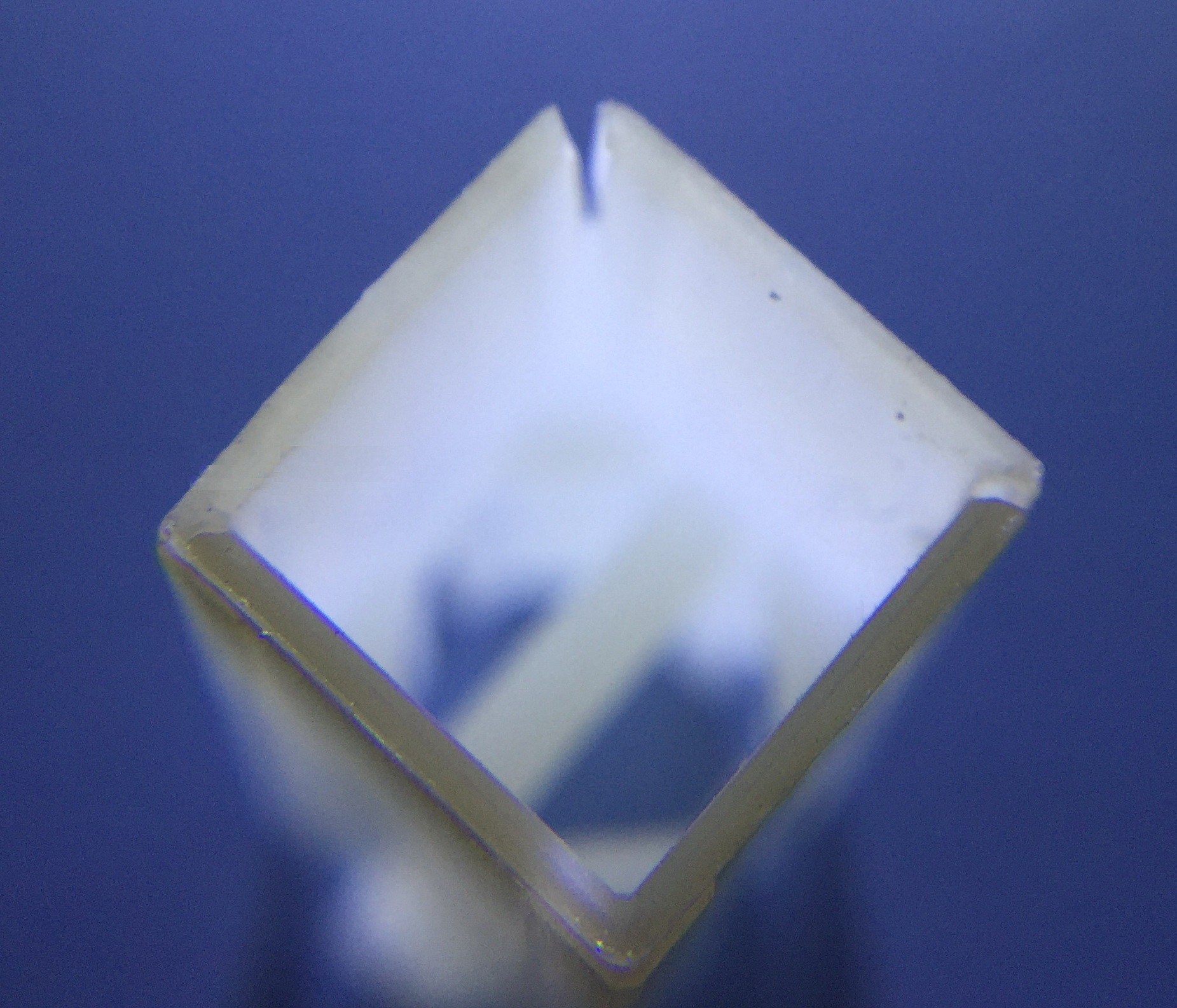
One of the common problems with the HP-85 computers is that the plungers for the keyboards deteriorate over time. They have a square hollow cross section. Over time, many of these plungers develop cracks in the corners leading the wall of the plunger to bend away from the stem of the key cap.
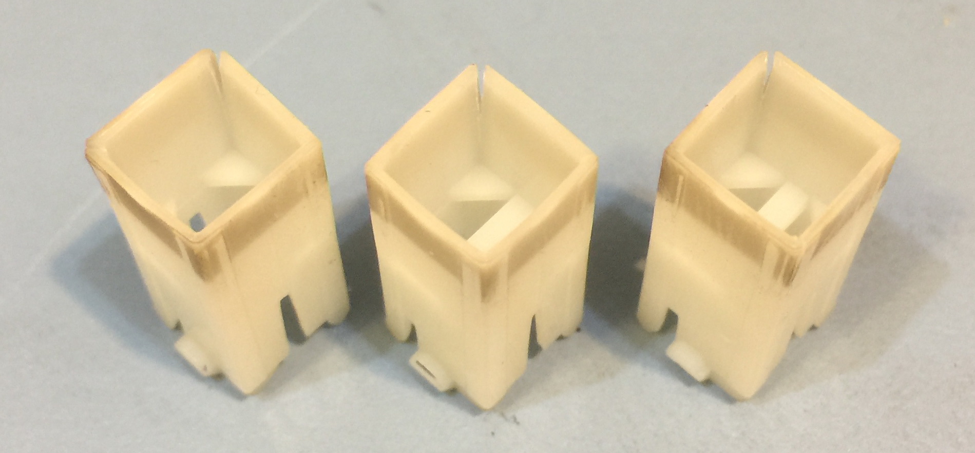
Three typical white plungers with cracks in one or more corners. The dark band at the the top of each plunger is just dirt.
The key cap stem is inserted into the square hole. The key cap stem has a slightly tapered profile, and when fully inserted (as designed) it places pressure on the walls of the plunger. Combined with aging of the plastic that makes it more brittle, this is probably the cause of the cracks that develop over several decades.
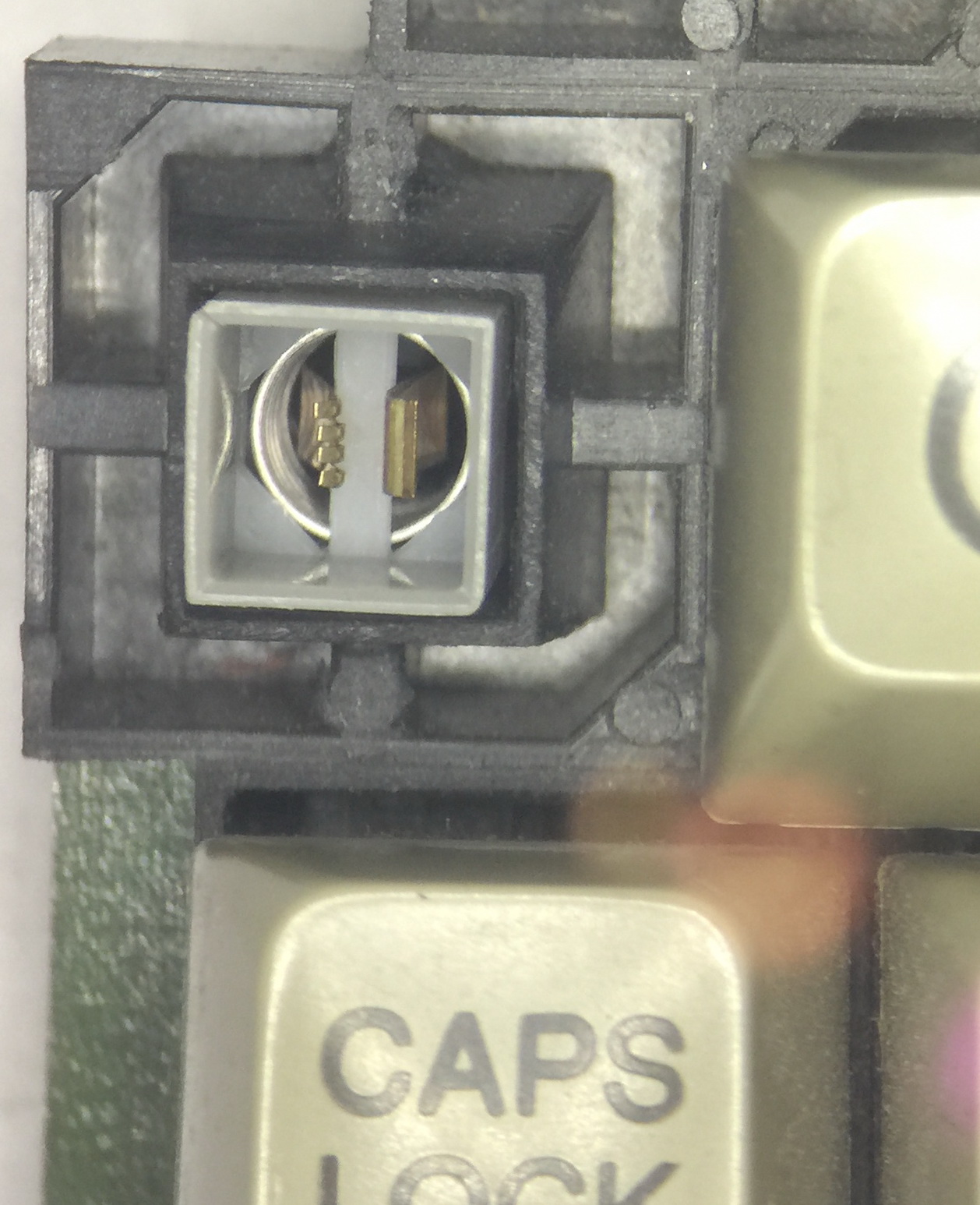
The plunger slides vertically within a well in a black plastic housing that includes the key switch contacts.
The switch contact are soldered into a Printed Circuit Board (PCB) that is on the back of the black plastic housing.
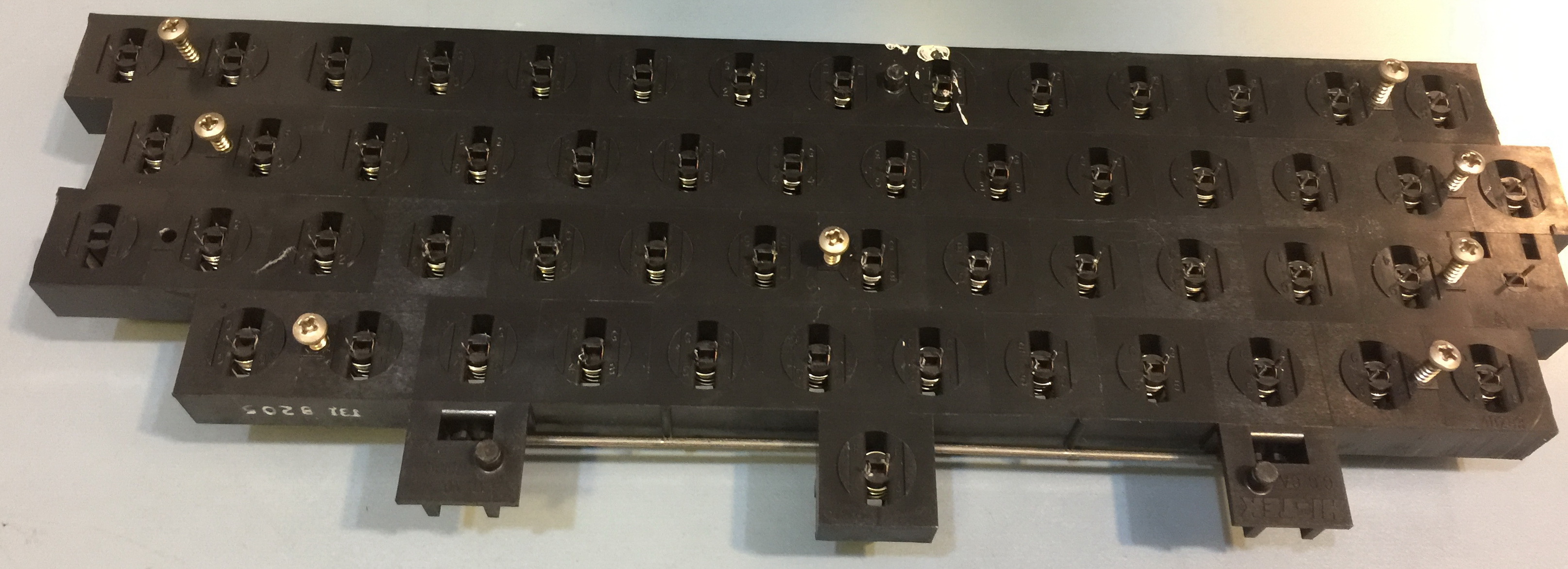
There are several black plastic housings, a few that hold 1 to 5 keys, mostly along the top row of the key board, the numeric key pad with 20 keys, and the remaining 54 keys go into a single large black plastic housing. The black plastic housings can’t be removed from the the printed circuit board (PCB) without un-soldering all the switch contacts. (This picture is the back of the main black plastic housing, after un-soldering all 108 contacts.) Getting to the back of the black plastic housing may be desirable to assist in removing the plungers from the housing without breaking them.
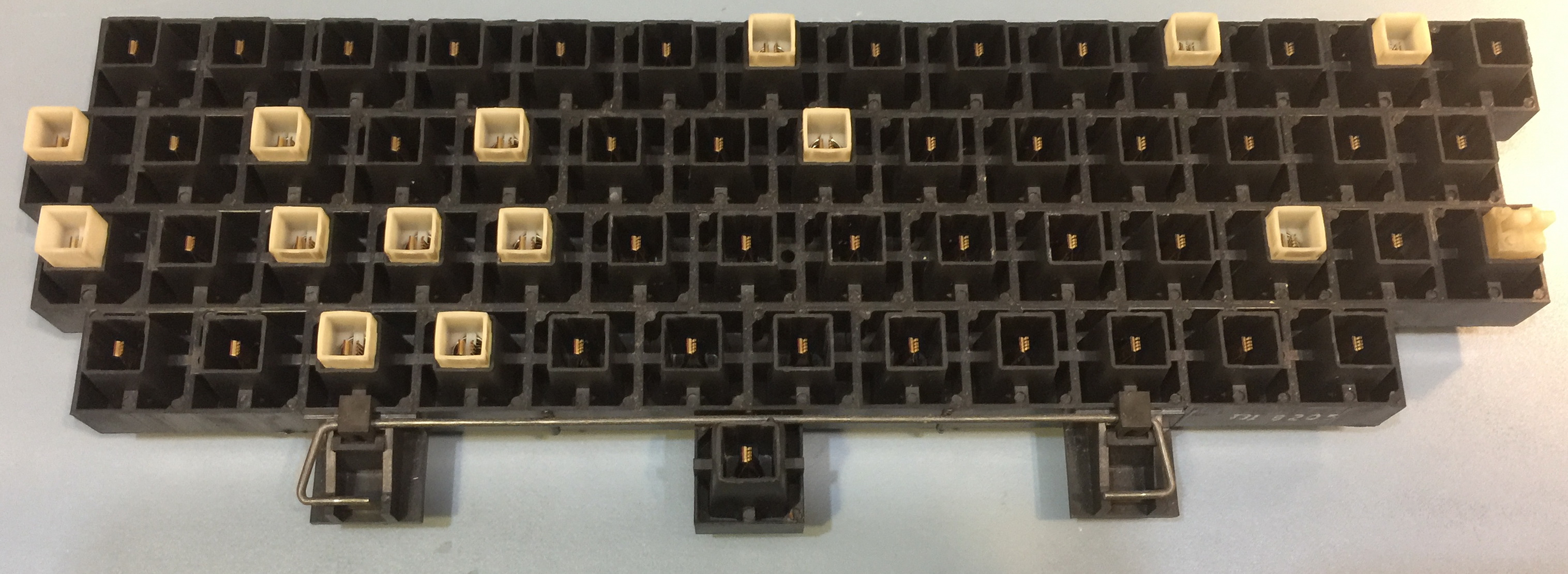
This is the front of my keyboard after removing the PCB and all the plungers that have cracks.
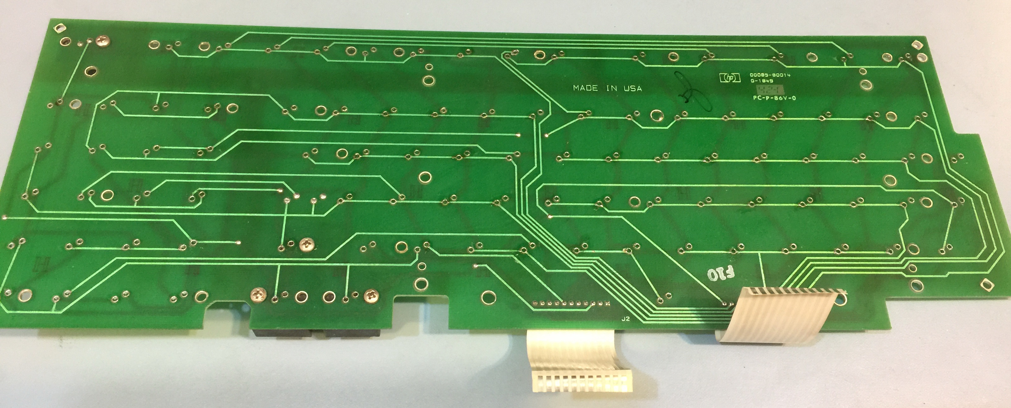
This is the back of the keyboard printed circuit board.
Series80 Forum Posts about Keyboard Plungers
Various online resources suggest that replacement plungers may be harvested from other keyboards (non HP-85), among them certain Atari and TI- 99/4A computers. Link to related Forum Posts
As the forum post notes, these computers are manufacture with several types of keyboard switches, so when you buy one, you may not get HP-85 compatible switches and plungers.
- One of the author states of the forum posts states that “The only known fix is to replace that square tube”
Challenge accepted!
Three types of Keyboard Plungers
I have seen 3 types of Plungers.
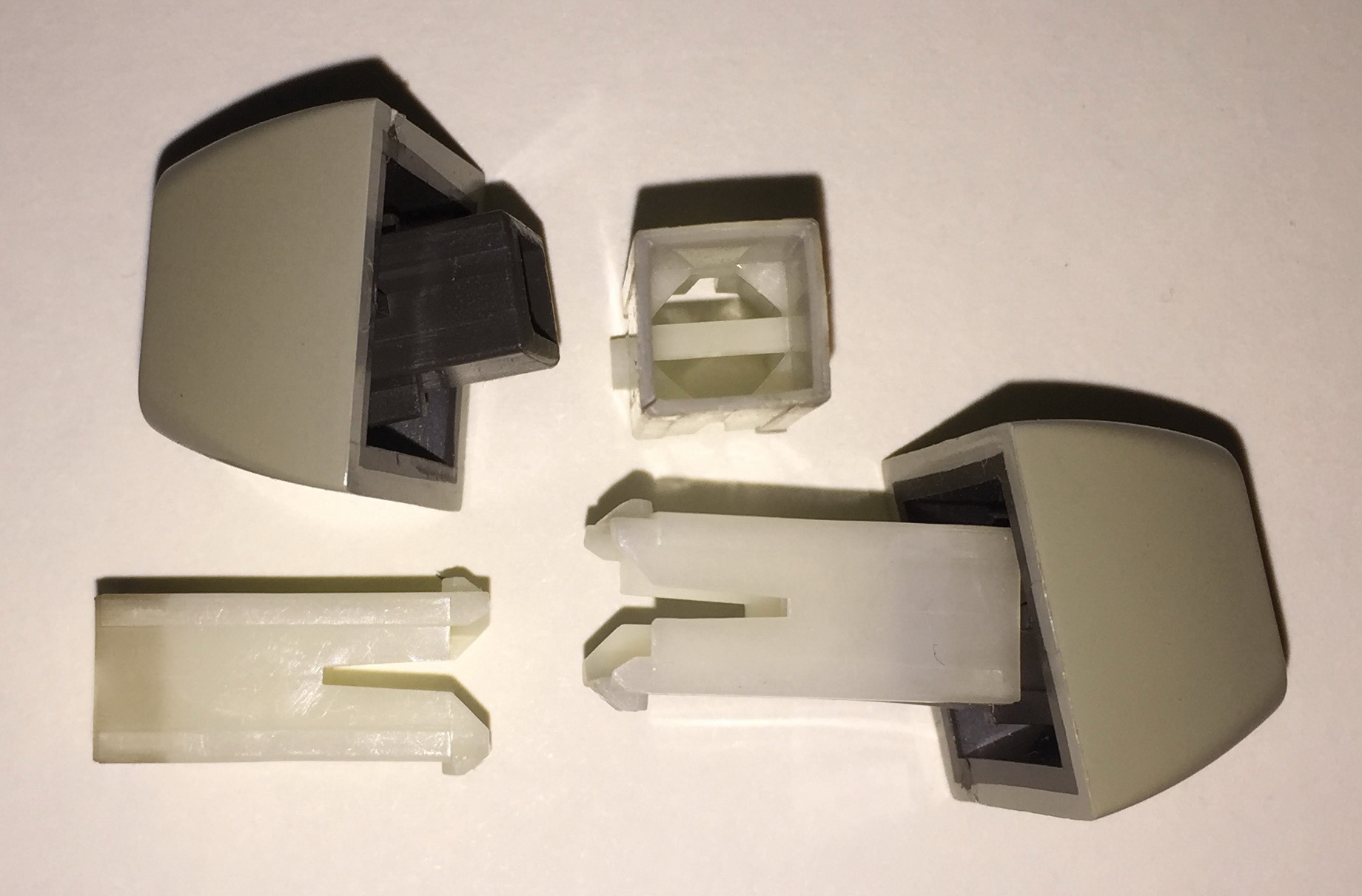
White plastic, with glide surfaces at the corners.
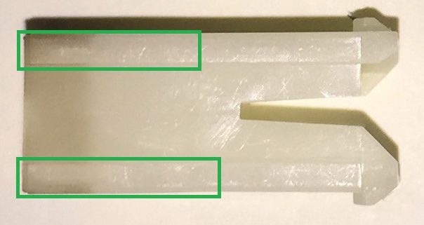
The bulk of my repair adventures were with this type of white plunger,
as my keyboard with this type of plunger had most of the keys getting
stuck because of the cracks.
Repair of these plungers is described here
White Plungers
Green plastic, with retaining tabs in the wrong location.
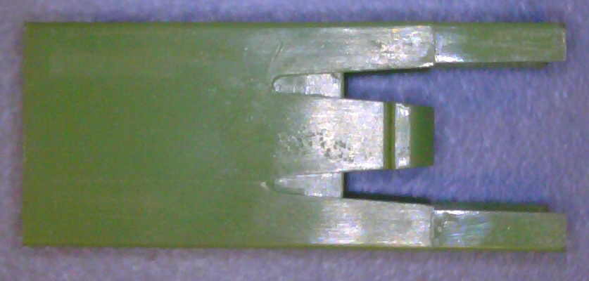
The TI-99/4A that I bought came with these Stackpole Green plungers that are not compatible with the HP-85. But the plastic they are made of seems to be of far better quality than the Hi-Tek plungers used in the HP-85 keyboards. They do not have any sign of deterioration. Your mileage may vary, etc.
Modifying these plungers to fit into the HP-85 keyboard are described here Green Plungers
White plastic, without glide surfaces at the corners.
My keyboard with this type of plunger had cracks in the corners too, but not as significant damage that the keys got stuck. This may change in the future. As the previous described plungers involved a very significant amount of time to repair, I was not motivated to take on another keyboard, where the problems of the cracks were not causing problems (yet).
I do not have a process for repairing these plungers.
Removing Plungers from the Keyboard (Success)
This section describes the manufacturing of a special tool to help remove the white plastic plungers from the black plastic housing. The PCB needs to be removed from the black plastic housing to use this tool, which entails un-soldering all the switch contacts. See Hakko FR-301-03/P Desoldering Tool
The tool is pressed into the back of the black plastic housing and presses the two retaining tabs toward each other, thus disengaing from the black plastic area that they are normally seated in. When using the tool, after insertion in the appropriate location, some additional wiggling may be required to get the tabs to move and for the plunger to be removed.
Like all pictures on this page, click the image for a larger version.
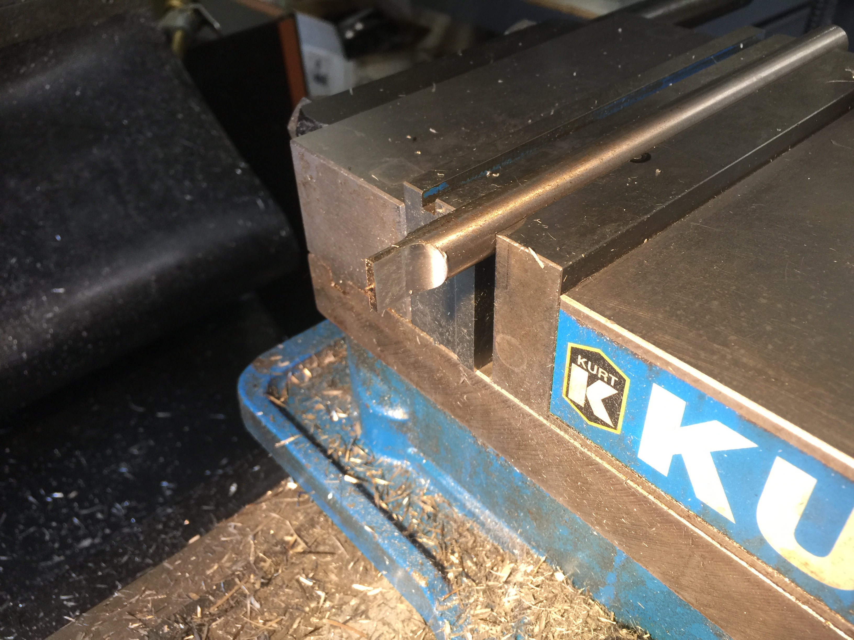
0.500” diameter 7” long W-1 tool steel (any steel grade would do for this application). Two vertical cuts are made, leaving a center piece that is 0.100” by 0.500”
Another view after the initial two cuts
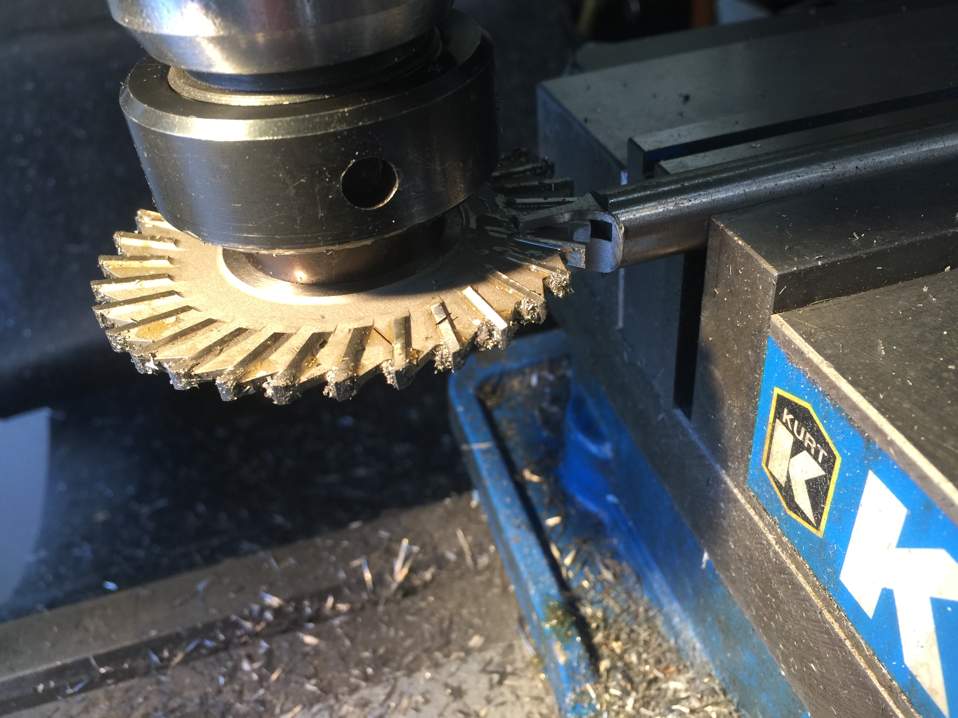
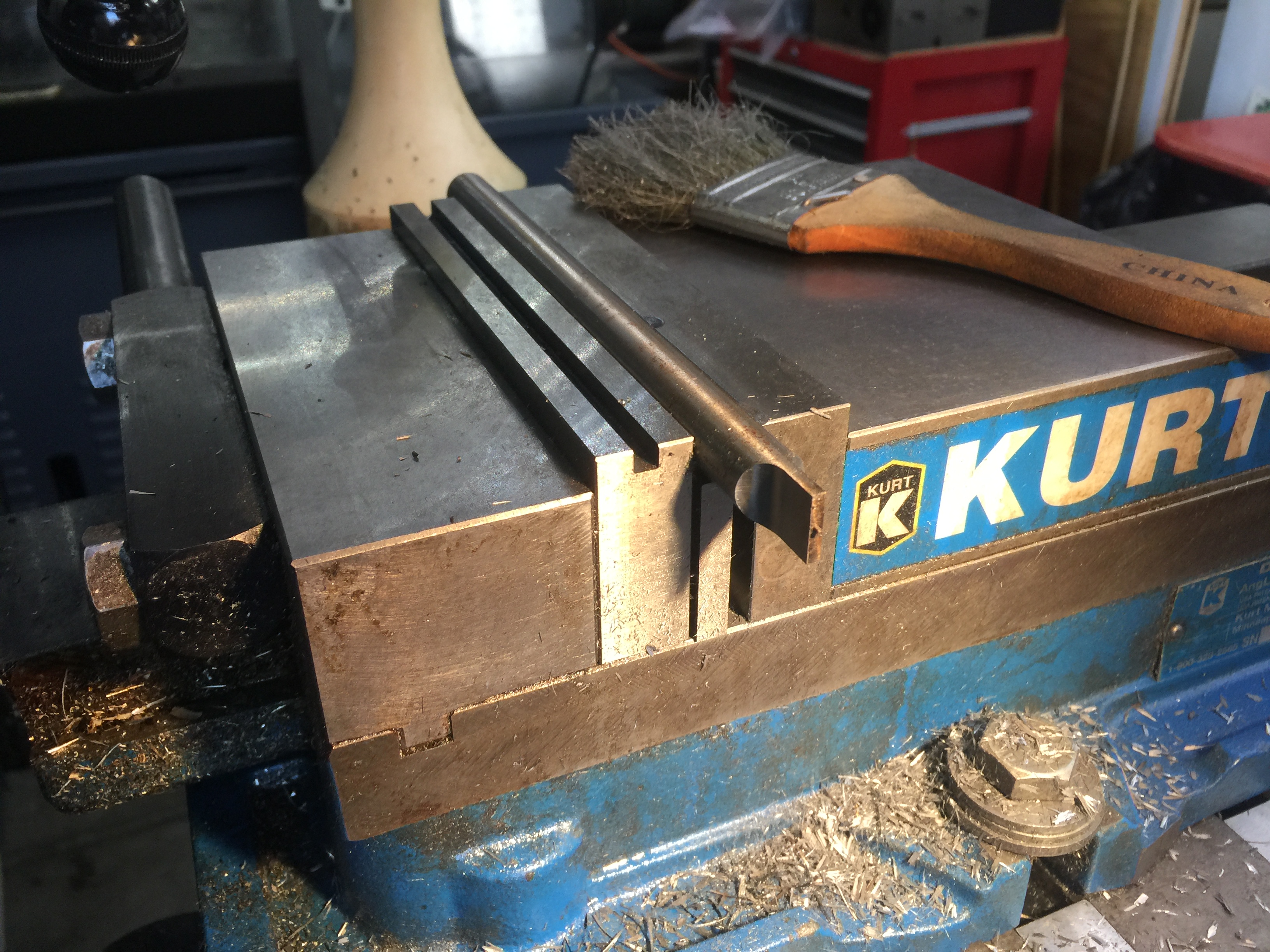
A slitting saw is used to remove 0.035” at the top and bottom of the part we are making. 0.300” is removed from the middle, leaving two prongs that are 0.100” wide and 0.065 high.
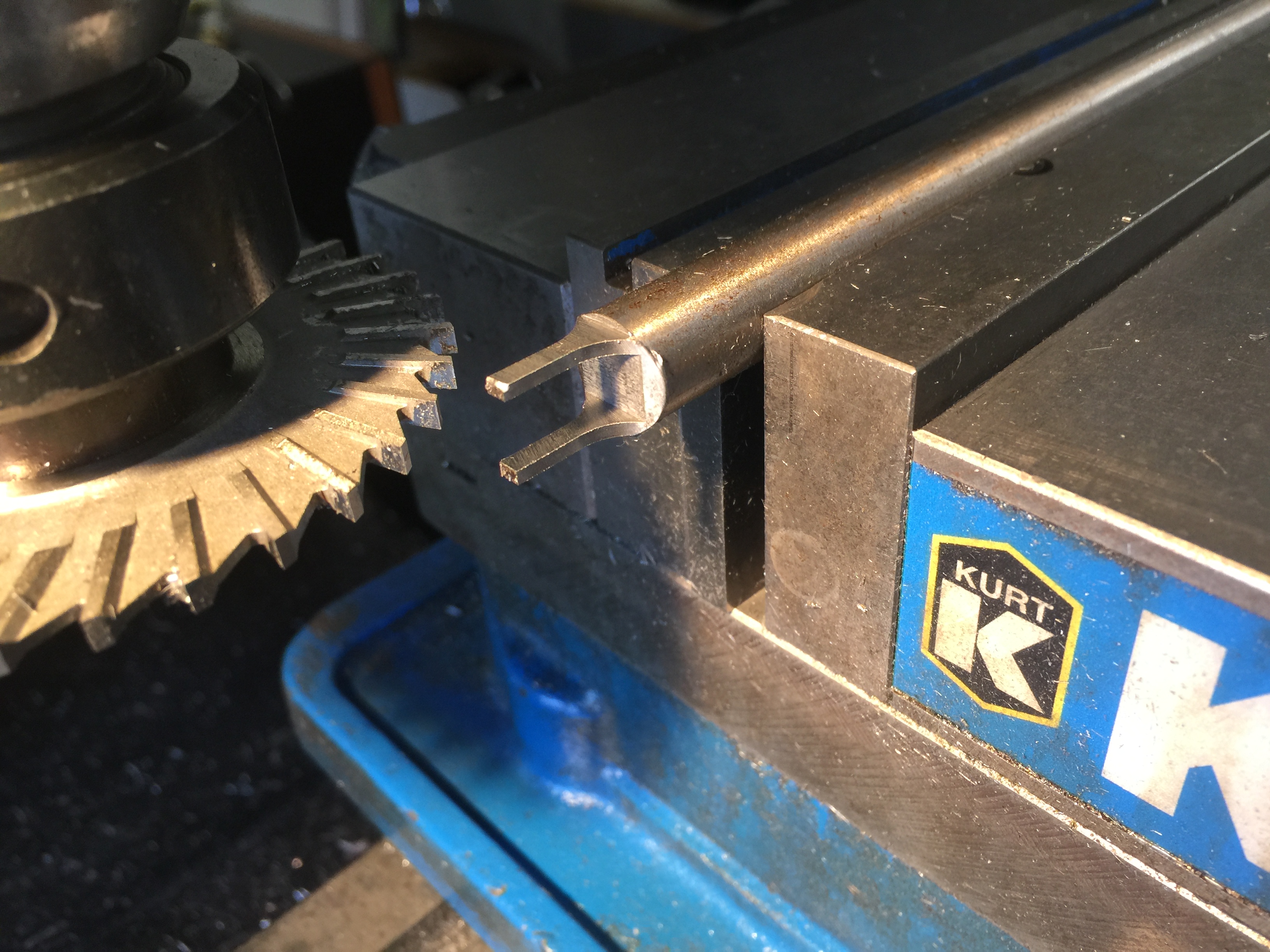
The milling of the tool is completed. Some manual filing is done at the tips create an internal chamfer, so that when pushed into the back of the black plastic keyboard housing (after the PCB has been removed), it will push the two retaining tabs of the white plunger towards each other, and allow the plunger to be removed without damaging the plunger
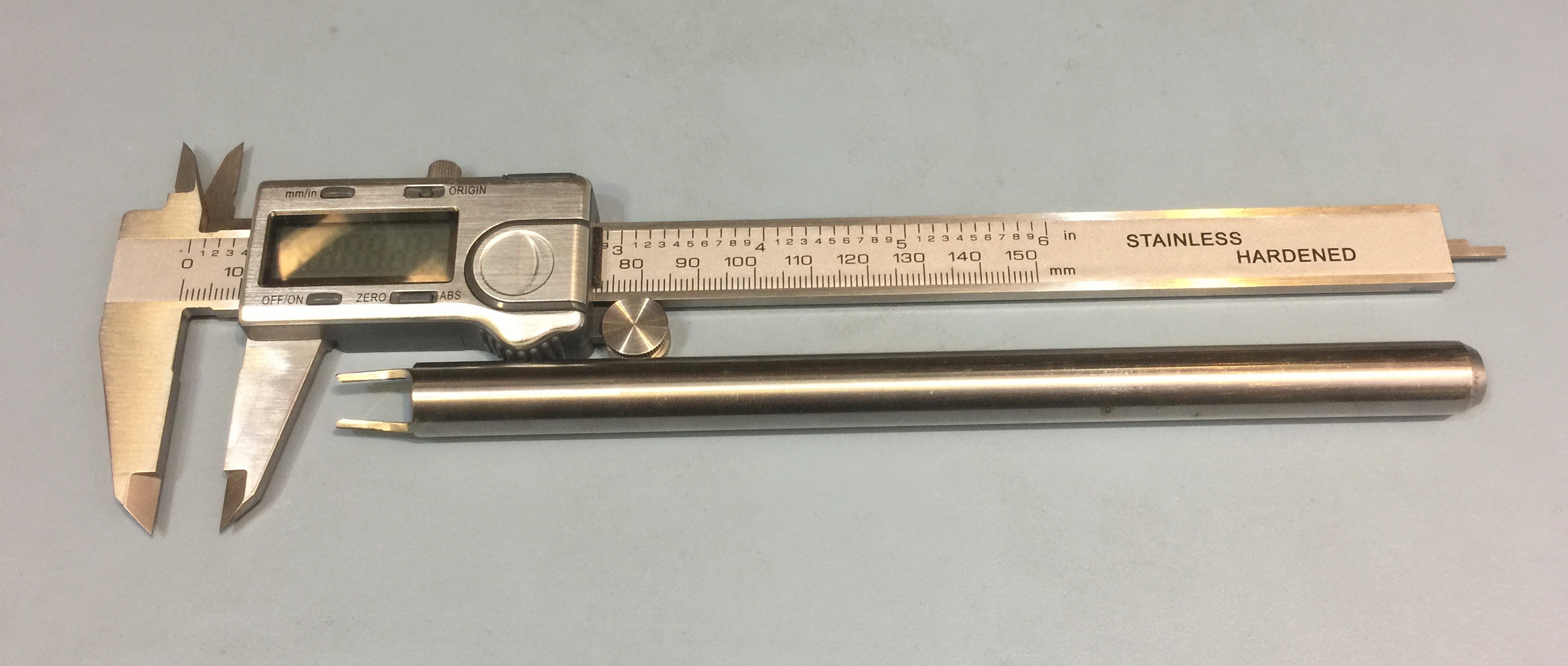
The finished tool adjacent to a 6” caliper for scale. Note that the two tips may need to be bent slightly towards each other to properly engage the plunger retaining tabs.
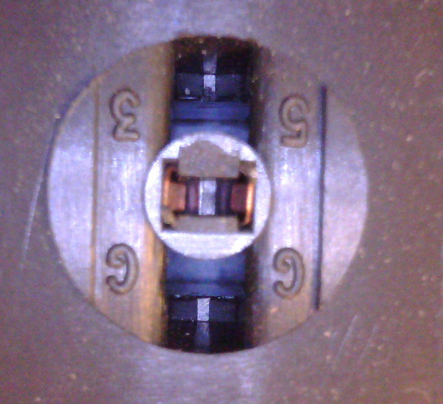
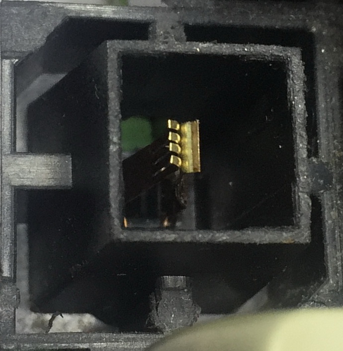
The back of the black keyboard housing after the PCB has been removed, with a focus on the area that the retaining tabs engage the black plastic. The plunger has already been remove, so what we see is the area that the retaining tab fits into.
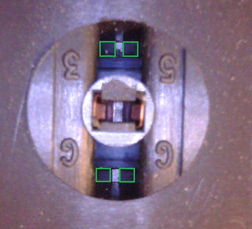
This image highlights in green the slopped sides of the area that the retaining tabs on the white plungers will be touching, when the key is not being pressed. Because of the shape of the tabs on the white plungers, the whole of the slopped surface is in contact with the tab.

Because of the different shape of the retaining tabs on the green plungers, after the modifications described here Green Plungers that moves the green tabs to a more appropriate position, the contact area is indicated by the green lines.