EBTKS Overview
The Origin story for EBTKS
(A first person perspective by Philip Freidin. July/August 2020)
This project started off as an attempt to repair the tape drive of an HP-85A desktop computer. Most of these tape drives (maybe all) have failed because the rubber capstan that moves the magnetic tape in the DC100/HP98200A cartridges have either disintegrated or turned into goo. My companion web site documents my Repair Adventures .
Eventually I decided that the repair of the tape drives and the tapes was a lost cause, so I decided that I would design a Solid State Tape Drive replacement that would be compatible with the existing HP85 operating system, and be responsive to all the same commands. I discussed this with my long time friend Russell Bull, and together we have co-designed the hardware and the firmware to make it all work. During our development work, we turned to Everett Kaser for guidance and he soon joined our team and is responsible for the AUXROMs, which added extensive functionality in the form of over 70 new keywords.
At 2:00 AM on 02/22/2020, I wrote the following to Russell via Skype (lightly edited for PC correctness.):
You know, if we put a Teensy 4.0 (600 MHz A7 Dual issue CPU !!!)
on an I/O board, it should be more than enough to bit-bang 1.6 us
bus cycles, not only could we do solid state replacement of the
tape drive, but some of the 2MB of FLASH could be 8 or more ROMS
(8 kB each), and we could also use some of the 1 MB of SRAM to
implement the 16 kB RAM module. Could also do ADC/DAC as discussed,
may as well do a RS232 serial interface, and expose I2C and SPI
and a proto area. USB comes along for the ride, Since it is
supported in Arduino land, could also offer it as a CPU offload
engine  :-) , using the 85 for keyboard, screen, and printer.  My
mind is a-buzz with possibilities, and most are just software that
can be done after the fact.  So BOM is for Teensy 4.0, PCB, level
shifters, RS232 cvt and connector, crappy ADC (only ~1 MSPS), no
DAC, but does have I2S and SPDIF....... CAN?, SD card, I2C and SPI
pins? parallel port pins? Some flashing lights :-), PWM? RTC.  I'm
done for this message..
Very quickly, Russell did the initial designed of version 1.0 hardware (with a different code name) that was the basis for our initial feature set discussions. We manufactured the PCB concurrently with an extender board design (for the HP-85 I/O bus) and had a working prototype by the end of March. We then spent about 3 months working on the firmware, and finding various issues due to our initial design decisions. Most of these were related to not having enough I/O pins on the Teensy 4.0 . Around late May we decided to redesign the board and remove multiple features that we realized we would be unlikely to take advantage of, but more importantly we changed the processor module to the just released Teensy 4.1 that you now see in EBTKS V2.0.
4 months later, you can read a pre-pre-pre announcement of EBTKS, and see that most of the top level design decisions Forum thread
Along the way we had discussions with various people with more experience with the Series 80 computers (prior to this project neither Russell or I had ever used one), and by far the most helpful is Everett Kaser. He is now a valuable member of the team, and has worked on creating the AUXROM(s) that allow many of the features of EBTKS to be realized.
In August, Bob Armstrong joined in to do the first retro-computer add-on.
Like all pictures on this page, click the image for a larger version.
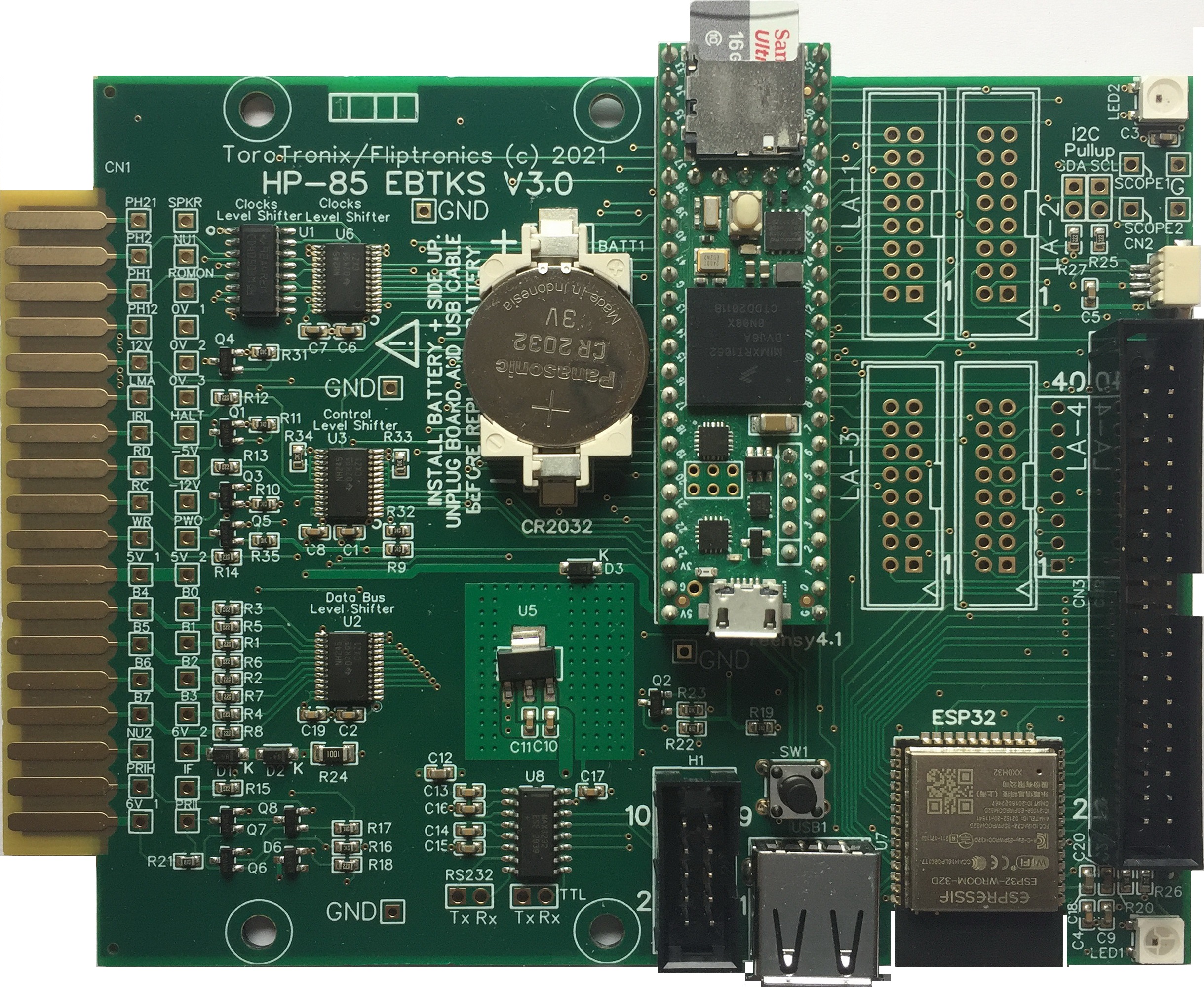
Production build of V3.0 EBTKS
Buying EBTKS
EBTKS is out of stock, the following link is to a page that describes how to be added to a wait list
EBTKS Feature List
Provided Services
Tape drive emulation, using the 16 GB SD card to store Tape images. Theoretically the SD card could hold about 200,000 tape images. To use this service, the existing tape drive must be disabled by unplugging the two flat-flex cables.
To help you decide about this, please see Tape Drive Strategies with EBTKSDisk drive emulation, using the 16 GB SD card to store Disk images. The number of disk images will depend on whether the emulated disk is a floppy or Winchester disk drive. We hope to support multiple disk drive types.
RAM to fill the top 16 kB of the HP-85A.
Up to 256 kB of Extended memory for HP85B (EDISK), and HP86/87 computers
EBTKS provides for up to 18 ROMs to be loaded from the SD card under control of the CONFIG.TXT file. Due to constraints imposed by the System ROMs, only 14 option ROMs are supported (one is system ROM 0). This is sufficient for all 12 standard published Option ROMs. The remainder of the 18 ROMs use a special facility for AUXROMs, discussed later. Currently there are four required AUXROMs which specifically supports EBTKS.
No Jumper configuration. Configuration of options (like which ROMs are active, initial tape/disk image loaded) is under control of an easily editable CONFIG.TXT file on the SD card.
Direct access to the CRT to move cursor and read/write text
Improved auto-start program can include multiple commands or a simple batch file.
Only requires 1 slot in the I/O backplane
HELP facility (still in development)
EBTKS Console using serial-over-USB
Other features are still in development
Over 70 New Keywords
Hardware Resources
600 MHz Cortex M7 processor
Processor is an NXP IMXRT1062
Processor module is a Teensy 4.1
1 MB high speed On-Chip RAM
8 MB medium speed RAM external to the processor
Device USB port used for firmware update and diagnostic serial
Host USB port for USB Keyboard and maybe other devices
16 GB SD Card
Two multi color LEDs
Support for I2C add on boards via QWIIC at SparkFun , QWIIC at Smart Prototyping
Optional ESP32 Processor module WROOM-32D. (Under development)
ESP32-D0WD
32 MBits SPI Flash (4 MByte)
448 kB ROM for boot and core library
520 kB SRAM
8+8 kB SRAM in RTC (could be (but isn’t yet) battery backed up)
1 Kbit of eFuse (single programming)
40 MHz crystal
2 x CPUs (Xtensa LX6) at 80 to 240 MHz
FPU & DSP
PCB Antenna
Radio
Wifi 802.11 b/g/n
BlueTooth V4.2 BR/EDR
BlueTooth Low Energy
ADC (poor quality)
DAC (8 bit)
SPI
I2C
I2S
UART
Ethernet
CAN bus
PWM
All spare I/O signals from both Teensy 4.1 and ESP32 modules go to a 40 pin Header
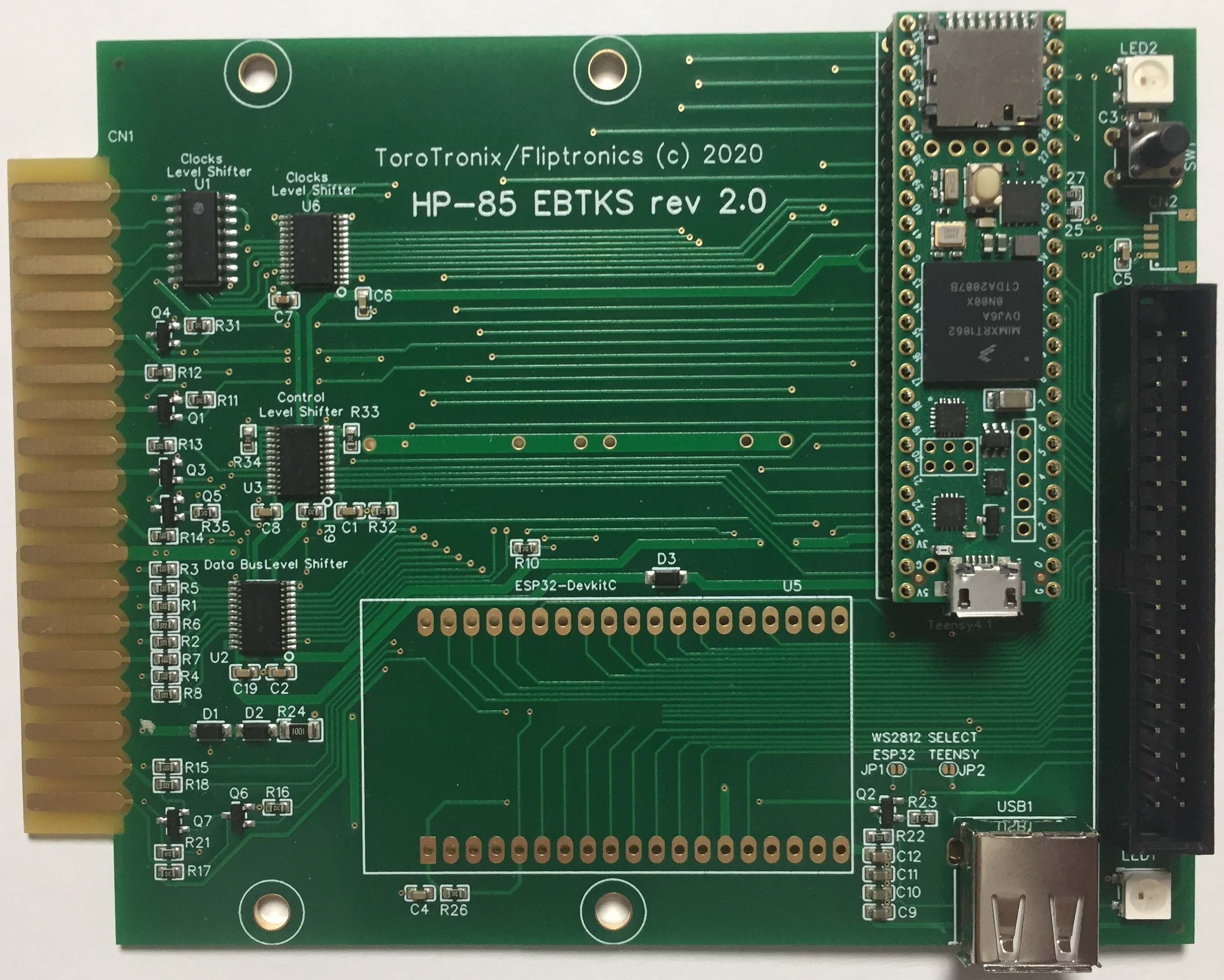
Prototype V2.0 used for most software development
Prototype V2.0 EBTKS standard configuration
(image is missing the SD Card and the QWIIC connector)
Prototype V2.0 EBTKS with optional ESP32 module
(image is missing the SD Card and the QWIIC connector)
